Cisco CCNA – Call Manager Express Part 1
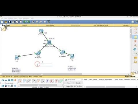
Build the following topology in packet tracer. After testing our configuration, we will deploy on devices.
Step 1) Create the VLANS
Switch#sh vlan br
| VLAN | Name | Status | Ports |
| 1 | default | active | Fa0/1, Fa0/2, Fa0/3, Fa0/4
Fa0/5, Fa0/6, Fa0/7, Fa0/8 Fa0/9, Fa0/10, Fa0/11, Fa0/12 Fa0/13, Fa0/14, Fa0/15, Fa0/16 Fa0/17, Fa0/18, Fa0/19, Fa0/20 Fa0/21, Fa0/22, Fa0/23, Fa0/24 Gig0/1, Gig0/2 |
| 1002 | fddi-default | active | |
| 1003 | token-ring-default | active | |
| 1004 | fddinet-default | active | |
| 1005 | trnet-default SW1# | active |
Initially there are no VLAN’s defined
Create three VLANS:
VLAN 40 Name DATA
VLAN 41 Name Management
VLAN 45 Name VOICE
Switch#conf t
Enter configuration commands, one per line. End with CNTL/Z.
Switch(config)#vlan 40
Switch(config-vlan)#name DATA
Switch(config-vlan)#vlan 41
Switch(config-vlan)#name Management
Switch(config-vlan)#VLAN 45
Switch(config-vlan)#name VOICE
Switch(config-vlan)#
Switch#sh vlan br
Receive our Cisco CCNA Packet Tracer!
Get our complete tutorial in PDF
| VLAN | Name | Status | Ports |
| 1 | default | active | Fa0/1, Fa0/2, Fa0/3, Fa0/4
Fa0/5, Fa0/6, Fa0/7, Fa0/8 Fa0/9, Fa0/10, Fa0/11, Fa0/12 Fa0/13, Fa0/14, Fa0/15, Fa0/16 Fa0/17, Fa0/18, Fa0/19, Fa0/20 Fa0/21, Fa0/22, Fa0/23, Fa0/24 Gig0/1, Gig0/2 |
| 40 | DATA | active | |
| 41 | Management | active | |
| 45 | VOICE | active | |
| 1002 | fddi-default | active | |
| 1003 | token-ring-default | active | |
| 1004 | fddinet-default | active | |
| 1005 | trnet-default | active |
Now we need to assign ports (fa0/2 – 24) to the VLAN’s (both voice and data vlan’s).
Hint: Do not include port fa0/1 since it is connected to the router and it needs to be a Trunk.
Switch#conf t
Enter configuration commands, one per line. End with CNTL/Z.
Switch(config)#int range fa0/2 – 24
Switch(config-if-range)#sw
Switch(config-if-range)#switchport mo
Switch(config-if-range)#switchport mode acce
Switch(config-if-range)#switchport mode access
Switch(config-if-range)#sw
Switch(config-if-range)#switchport acc
Switch(config-if-range)#switchport access vl
Switch(config-if-range)#switchport access vlan 40
Switch(config-if-range)#sw
Switch(config-if-range)#switchport voi
Switch(config-if-range)#switchport voice vl
Switch(config-if-range)#switchport voice vlan 45
Switch(config-if-range)#
Switch(config-if-range)#^Z
Switch#
%SYS-5-CONFIG_I: Configured from console by console
Switch#sh vlan brief
| VLAN | Name | Status | Ports |
| 1 | default | active | Fa0/1, Gig0/1, Gig0/2
|
| 40 | DATA | active | Fa0/2, Fa0/3, Fa0/4, Fa0/5
Fa0/6, Fa0/7, Fa0/8, Fa0/9 Fa0/10, Fa0/11, Fa0/12, Fa0/13 Fa0/14, Fa0/15, Fa0/16, Fa0/17 Fa0/18, Fa0/19, Fa0/20, Fa0/21 Fa0/22, Fa0/23, Fa0/24 |
| 41 | Management | active | |
| 45 | VOICE | active | Fa0/2, Fa0/3, Fa0/4, Fa0/5 Fa0/6, Fa0/7, Fa0/8, Fa0/9 Fa0/10, Fa0/11, Fa0/12, Fa0/13 Fa0/14, Fa0/15, Fa0/16, Fa0/17 Fa0/18, Fa0/19, Fa0/20, Fa0/21 Fa0/22, Fa0/23, Fa0/24 |
| 1002 | fddi-default | active | |
| 1003 | token-ring-default | active | |
| 1004 | fddinet-default | active | |
| 1005 | trnet-default | active |
NOTE: Packet Tracer does not display the ports for the VOICE vlan; however, it is functional.
Here is the show run output for the interfaces:
!
!
!
!
!
!
spanning-tree mode pvst
!
!
!
!
!
!
interface FastEthernet0/1
!
interface FastEthernet0/2
switchport access vlan 40
switchport mode access
switchport voice vlan 45
!
interface FastEthernet0/3
switchport access vlan 40
switchport mode access
switchport voice vlan 45
!
interface FastEthernet0/4
switchport access vlan 40
switchport mode access
switchport voice vlan 45
!
interface FastEthernet0/5
switchport access vlan 40
switchport mode access
switchport voice vlan 45
!
interface FastEthernet0/6
switchport access vlan 40
switchport mode access
switchport voice vlan 45
!
interface FastEthernet0/7
switchport access vlan 40
switchport mode access
switchport voice vlan 45
!
interface FastEthernet0/8
switchport access vlan 40
switchport mode access
switchport voice vlan 45
!
interface FastEthernet0/9
switchport access vlan 40
switchport mode access
switchport voice vlan 45
!
interface FastEthernet0/10
switchport access vlan 40
switchport mode access
switchport voice vlan 45
!
interface FastEthernet0/11
switchport access vlan 40
switchport mode access
switchport voice vlan 45
!
interface FastEthernet0/12
switchport access vlan 40
switchport mode access
switchport voice vlan 45
!
interface FastEthernet0/13
switchport access vlan 40
switchport mode access
switchport voice vlan 45
!
interface FastEthernet0/14
switchport access vlan 40
switchport mode access
switchport voice vlan 45
!
interface FastEthernet0/15
switchport access vlan 40
switchport mode access
switchport voice vlan 45
!
interface FastEthernet0/16
switchport access vlan 40
switchport mode access
switchport voice vlan 45
!
interface FastEthernet0/17
switchport access vlan 40
switchport mode access
switchport voice vlan 45
!
interface FastEthernet0/18
switchport access vlan 40
switchport mode access
switchport voice vlan 45
!
interface FastEthernet0/19
switchport access vlan 40
switchport mode access
switchport voice vlan 45
!
interface FastEthernet0/20
switchport access vlan 40
switchport mode access
switchport voice vlan 45
!
interface FastEthernet0/21
switchport access vlan 40
switchport mode access
switchport voice vlan 45
!
interface FastEthernet0/22
switchport access vlan 40
switchport mode access
switchport voice vlan 45
!
interface FastEthernet0/23
switchport access vlan 40
switchport mode access
switchport voice vlan 45
!
interface FastEthernet0/24
switchport access vlan 40
switchport mode access
switchport voice vlan 45
!
Step 2) Enabling the Trunk Port
Since traffic for multiple vlan’s are carried to the router, we need to make sure the link connecting to the router from the switch is a Trunk.
Switch#conf t
Enter configuration commands, one per line. End with CNTL/Z.
Switch(config)#int fa0/1
Switch(config-if)#sw
Switch(config-if)#switchport mod
Switch(config-if)#switchport mode ?
access Set trunking mode to ACCESS unconditionally
dynamic Set trunking mode to dynamically negotiate access or trunk mode
trunk Set trunking mode to TRUNK unconditionally
Switch(config-if)#switchport mode tr
witch(config-if)#switchport mode trunk
Command rejected: An interface whose trunk encapsulation is “Auto” can not be configured to “trunk” mode.
Switch(config-if)#
Switch(config-if)#
Switch(config-if)#sw
Switch(config-if)#switchport tr
Switch(config-if)#switchport trunk ?
allowed Set allowed VLAN characteristics when interface is in trunking
mode
encapsulation Set trunking encapsulation when interface is in trunking mode
native Set trunking native characteristics when interface is in
trunking mode
Switch(config-if)#switchport trunk enc
Switch(config-if)#switchport trunk encapsulation ?
dot1q Interface uses only 802.1q trunking encapsulation when trunking
Switch(config-if)#switchport trunk encapsulation dot
Switch(config-if)#switchport trunk encapsulation dot1q
Switch(config-if)#sw
Switch(config-if)#switchport mo
Switch(config-if)#switchport mode tr
Switch(config-if)#switchport mode trunk
Switch(config-if)#
As can be seen, we can not configure the port to be a Trunk if it is in the Auto encapsulation. First we need to set the encapsulation to dot1q.
Here is the show run output:
!
interface FastEthernet0/1
switchport trunk encapsulation dot1q
switchport mode trunk
!
On the router, enable to fa0/0 interface with the no shutdown command. Verify the status of the Trunk on the switch.
Switch#sh int trunk
| Port | Mode | Encapsulation | Status | Native vlan |
| Fa0/1 | on | 802.1q | trunking | 1 |
Port Vlans allowed on trunk
Fa0/1 1-1005
Port Vlans allowed and active in management domain
Fa0/1 1,40,41,45
Port Vlans in spanning tree forwarding state and not pruned
Fa0/1 1,40,41,45
Step 3) Configure the router
We have multiple vlan traffic destined to the router (Default Gateway) being carried over the Trunk interface. We need to support multiple default gateways, but only have one interface. The solution here is to use sub-interfaces in a topology known as “Router on a Stick”.
Hint: IP addressed are assigned on the sub-interfaces and not the physical interface
R1(config)#int fa0/0.40
R1(config-subif)#
%LINK-5-CHANGED: Interface FastEthernet0/0.40, changed state to up
%LINEPROTO-5-UPDOWN: Line protocol on Interface FastEthernet0/0.40, changed state to up
R1(config-subif)#enc
R1(config-subif)#des
R1(config-subif)#description Default Gateway for DATA vlan 40
R1(config-subif)#enc
R1(config-subif)#encapsulation dot
R1(config-subif)#encapsulation dot1Q 40
R1(config-subif)#ip add 10.40.0.1 255.255.255.0
R1(config-subif)#
R1(config-subif)#
R1(config-subif)#exit
R1(config)#int fa0/0.41
R1(config-subif)#
%LINK-5-CHANGED: Interface FastEthernet0/0.41, changed state to up
%LINEPROTO-5-UPDOWN: Line protocol on Interface FastEthernet0/0.41, changed state to up
R1(config-subif)#description Default Gateway for Management vlan 41
R1(config-subif)#ip add 10.41.0.1 255.255.255.0
% Configuring IP routing on a LAN subinterface is only allowed if that
subinterface is already configured as part of an IEEE 802.10, IEEE 802.1Q,
or ISL vLAN.
R1(config-subif)#encapsulation dot1Q 41
R1(config-subif)#ip add 10.41.0.1 255.255.255.0
R1(config-subif)#
R1(config-subif)#exit
R1(config)#int fa0/0.45
R1(config-subif)#
%LINK-5-CHANGED: Interface FastEthernet0/0.45, changed state to up
%LINEPROTO-5-UPDOWN: Line protocol on Interface FastEthernet0/0.45, changed state to up
R1(config-subif)#description Default Gateway for VOICE vlan 45
R1(config-subif)#encapsulation dot1Q 45
R1(config-subif)#ip add 10.45.0.1 255.255.255.0
R1(config-subif)#end
R1#
%SYS-5-CONFIG_I: Configured from console by console
NOTE 1: We first must identify which vlan the sub-interface belong to by using the encapsulation dot1Q command. The sub-interface number (i.e. fa0/0.XX) does not have to match the vlan ID ( it can be any number); however, the encapsulation dot1Q command must correctly match with the vlan ID.
NOTE 2: The ip address of the sub-interface is the Default Gateway address of that vlan.
Here is the show run:
!
interface FastEthernet0/0 (Note the is no ip address assigned to the physical interface)
no ip address
duplex auto
speed auto
!
interface FastEthernet0/0.40
description Default Gateway for DATA vlan 40
encapsulation dot1Q 40 (must match the vlan id)
ip address 10.40.0.1 255.255.255.0 (Default Gateway of DATA vlan 40)
!
interface FastEthernet0/0.41
description Default Gateway for Management vlan 41
encapsulation dot1Q 41
ip address 10.41.0.1 255.255.255.0
!
interface FastEthernet0/0.45
description Default Gateway for VOICE vlan 45
encapsulation dot1Q 45
ip address 10.45.0.1 255.255.255.0
!
Here is the output of the show ip int brief command
R1#sh ip int br]
| Interface | IP-Address | OK? | Method | Status | Protocol |
| FastEthernet0/0 | unassigned | YES | unset | up | up |
| FastEthernet0/0.40 | 10.40.0.1 | YES | manual | up | up |
| FastEthernet0/0.41 | 10.41.0.1 | YES | manual | up | up |
| FastEthernet0/0.45 | 10.45.0.1 | YES | manual | up | up |
The out of show ip route
R1#sh ip route
Codes: C – connected, S – static, I – IGRP, R – RIP, M – mobile, B – BGP
D – EIGRP, EX – EIGRP external, O – OSPF, IA – OSPF inter area
N1 – OSPF NSSA external type 1, N2 – OSPF NSSA external type 2
E1 – OSPF external type 1, E2 – OSPF external type 2, E – EGP
i – IS-IS, L1 – IS-IS level-1, L2 – IS-IS level-2, ia – IS-IS inter area
* – candidate default, U – per-user static route, o – ODR
P – periodic downloaded static route
Gateway of last resort is not set
10.0.0.0/24 is subnetted, 3 subnets
C 10.40.0.0 is directly connected, FastEthernet0/0.40
C 10.41.0.0 is directly connected, FastEthernet0/0.41
C 10.45.0.0 is directly connected, FastEthernet0/0.45
Step 4) Configure DHCP server on the Router
When configuring the DHCP server on the router, make sure you exclude the static ip address range first. We do not want the server to hand out static ip address range. Also, for voice applications, option 150 must be configured. This option point to the tftp server for Cisco Call Manager Express.
Hint: make use of the ios help feature by using ?, i.e. ip dhcp ?
R1#
R1#conf t
Enter configuration commands, one per line. End with CNTL/Z.
R1(config)#ip dhcp
R1(config)#ip dhcp ?
excluded-address Prevent DHCP from assigning certain addresses
pool Configure DHCP address pools
relay DHCP relay agent parameters
R1(config)#ip dhcp ex
R1(config)#ip dhcp excluded-address 10.40.0.1 10.40.0.10
R1(config)#ip dhcp
R1(config)#ip dhcp ?
excluded-address Prevent DHCP from assigning certain addresses
pool Configure DHCP address pools
relay DHCP relay agent parameters
R1(config)#ip dhcp poo
R1(config)#ip dhcp pool DATAPOOL
R1(dhcp-config)#?
default-router Default routers
dns-server Set name server
exit Exit from DHCP pool configuration mode
network Network number and mask
no Negate a command or set its defaults
option Raw DHCP options
R1(dhcp-config)#net
R1(dhcp-config)#network 10.40.0.0 ma
R1(dhcp-config)#network 10.40.0.0 ?
A.B.C.D Network mask
R1(dhcp-config)#network 10.40.0.0 255.255.255.0
R1(dhcp-config)#def
R1(dhcp-config)#default-router 10.40.0.1
R1(dhcp-config)#opt
R1(dhcp-config)#option ?
<0-254> DHCP option code
R1(dhcp-config)#option 150
% Incomplete command.
R1(dhcp-config)#option 150 ?
ip Data is one or more IP addresses
R1(dhcp-config)#option 150 ip ?
A.B.C.D Set IP address
R1(dhcp-config)#option 150 ip 10.40.0.1
R1(dhcp-config)#
Here is the show run:
!
ip dhcp excluded-address 10.40.0.1 10.40.0.10
!
ip dhcp pool DATAPOOL
network 10.40.0.0 255.255.255.0
default-router 10.40.0.1
option 150 ip 10.40.0.1
!
We need to repeat the above steps for the voice vlan.
R1#conf t
Enter configuration commands, one per line. End with CNTL/Z.
R1(config)#ip dhcp ex
R1(config)#ip dhcp excluded-address 10.45.0.1 10.45.0.10
R1(config)#ip dhcp
R1(config)#ip dhcp poo
R1(config)#ip dhcp pool VOICEPOOL
R1(dhcp-config)#net
R1(dhcp-config)#network 10.45.0.0 255.255.255.0
R1(dhcp-config)#def
R1(dhcp-config)#default-router 10.45.0.1
R1(dhcp-config)#optio
R1(dhcp-config)#option 150 ip 10.40.0.1
R1(dhcp-config)#
Here is the show run
!
!
ip dhcp excluded-address 10.40.0.1 10.40.0.10
ip dhcp excluded-address 10.45.0.1 10.45.0.10
!
ip dhcp pool DATAPOOL
network 10.40.0.0 255.255.255.0
default-router 10.40.0.1
option 150 ip 10.40.0.1
ip dhcp pool VOICEPOOL
network 10.45.0.0 255.255.255.0
default-router 10.45.0.1
option 150 ip 10.40.0.1
!
Step 5) Test Devices for correct ip address assignment from DHCP
At this time, we need to make sure that our devices, namely the phones and host computers, are assigned correct ip addresses. This can be achieved by checking if the DHCP server has handed out ip address, namely check for IP address to Mac address binding.
R1#sh ip dhcp binding
IP address |
Client-ID/Hardware address |
Lease expiration |
Type |
| 10.40.0.11 | 00D0.FF91.B4E5 | — | Automatic |
| 10.40.0.12 | 0005.5E88.7145 | — | Automatic |
| 10.45.0.11 | 000A.4134.6638 | — | Automatic |
| 10.45.0.12 | 00E0.F7A4.318E | — | Automatic |
On our host we can see the ip address assignment:


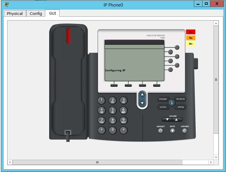
And the phone:

[bs_icon name=”glyphicon glyphicon-expand”] Watch the video and you will be able to understand Cisco Call Manager Express much better and Please subscribe to our YouTube Channel.


Want more information on how to become Cisco CCNA Certified? Learn more!
Join our Cisco CCNA facebook study group!
