Cisco CCNA VLAN Configuration
Setting up VLAN’s
On a new switch, all the ports are in VLAN 1 by default. We just plug in the Ethernet cables and the devices can communicate. Furthermore, all the ports are in the up/up (administratively up) mode.
SW1#show vlan bei
SW1#show vlan bri
SW1#show vlan brief
| VLAN | Name | Status | Ports |
| 1 | default | active | Fa0/1, Fa0/2, Fa0/3, Fa0/4
Fa0/5, Fa0/6, Fa0/7, Fa0/8 Fa0/9, Fa0/10, Fa0/11, Fa0/12 Fa0/13, Fa0/14, Fa0/15, Fa0/16 Fa0/17, Fa0/18, Fa0/19, Fa0/20 Fa0/21, Fa0/22, Fa0/23, Fa0/24 Gig1/1, Gig1/2 |
| 1002 | fddi-default | active | |
| 1003 | token-ring-default | active | |
| 1004 | fddinet-default | active | |
| 1005 | trnet-default SW1# | active |
Receive our Cisco CCNA Packet Tracer!
Get our complete tutorial in PDF
Creating a VLAN, requires 2 steps:
Step 1) Create all your VLAN’s
Step 2) Assign ports to the VLAN’s
In our LAB, we want to set up the following:
PC1=f0/1 will be in VLAN 2 (SALES)
PC2=f0/2 will be in VLAN 2 (SALES)
PC4=f0/4 will be in VLAN 3 (EGR)
PC5=f0/5 will be in VLAN 3 (EGR)
Step 1) Create all your VLAN’s
SW1#config t
Enter configuration commands, one per line. End with CNTL/Z.
SW1(config)#vlan ?
<1-1005> ISL VLAN IDs 1-1005
SW1(config)#vlan 2
SW1(config-vlan)#?
VLAN configuration commands:
exit Apply changes, bump revision number, and exit mode
name Ascii name of the VLAN
no Negate a command or set its defaults
SW1(config-vlan)#name sales
SW1(config-vlan)#exit
SW1(config)#
SW1(config)#
SW1(config)#
SW1(config)#
SW1(config)#
SW1(config)#vlan ?
<1-1005> ISL VLAN IDs 1-1005
SW1(config)#vlan 3
SW1(config-vlan)#name EGR
SW1(config-vlan)#
Now let’s check the work:
| VLAN | Name | Status | Ports |
| 1 | default | active | Fa0/1, Fa0/2, Fa0/3, Fa0/4
Fa0/5, Fa0/6, Fa0/7, Fa0/8 Fa0/9, Fa0/10, Fa0/11, Fa0/12 Fa0/13, Fa0/14, Fa0/15, Fa0/16 Fa0/17, Fa0/18, Fa0/19, Fa0/20 Fa0/21, Fa0/22, Fa0/23, Fa0/24 Gig1/1, Gig1/2 |
| 2 | Sales | active | |
| 3 | EGR | active | |
| 1002 | fddi-default | active | |
| 1003 | token-ring-default | active | |
| 1004 | fddinet-default | active | |
| 1005 | trnet-default | active |
As we see, all the ports are still in VLAN 1
step 2) Assign ports to the VLAN’s
SW1#config t
Enter configuration commands, one per line. End with CNTL/Z.
SW1(config)#int f0/1
SW1(config-if)#sw
SW1(config-if)#switchport mo
SW1(config-if)#switchport mode ?
access Set trunking mode to ACCESS unconditionally
dynamic Set trunking mode to dynamically negotiate access or trunk mode
trunk Set trunking mode to TRUNK unconditionally
SW1(config-if)#switchport mode acc
SW1(config-if)#switchport mode access
SW1(config-if)#sw
SW1(config-if)#switchport acc
SW1(config-if)#switchport access ?
vlan Set VLAN when interface is in access mode
SW1(config-if)#switchport access vlan ?
<1-1005> VLAN ID of the VLAN when this port is in access mode
SW1(config-if)#switchport access vlan ?
<1-1005> VLAN ID of the VLAN when this port is in access mode
SW1(config-if)#switchport access vlan 2 ?
<cr>
SW1(config-if)#switchport access vlan 2
SW1(config-if)#
Here is the show run so far:
SW1#show run
interface FastEthernet0/1
switchport access vlan 2
switchport mode access
!
interface FastEthernet0/2
!
interface FastEthernet0/3
Lets check the show vlan brief command:
SW1#show vlan brief
| VLAN | Name | Status | Ports |
| 1 | default | active | Fa0/2, Fa0/3, Fa0/4, Fa0/5
Fa0/6, Fa0/7, Fa0/8, Fa0/9 Fa0/10, Fa0/11, Fa0/12, Fa0/13 Fa0/14, Fa0/15, Fa0/16, Fa0/17 Fa0/18, Fa0/19, Fa0/20, Fa0/21 Fa0/22, Fa0/23, Fa0/24,Gig1/1 Gig1/2 |
| 2 | Sales | active | Fa0/1 |
| 3 | EGR | active |
As we see from the output, we have f0/1 in vlan 2; but remember we need to have f0/2=PC2 also in vlan 2.
SW1#config t
Enter configuration commands, one per line. End with CNTL/Z.
SW1(config)#int f0/2
SW1(config-if)#sw
SW1(config-if)#switchport mo
SW1(config-if)#switchport mode ?
access Set trunking mode to ACCESS unconditionally
dynamic Set trunking mode to dynamically negotiate access or trunk mode
trunk Set trunking mode to TRUNK unconditionally
SW1(config-if)#switchport mode acc
SW1(config-if)#switchport mode access
SW1(config-if)#sw
SW1(config-if)#switchport acc
SW1(config-if)#switchport access vla
SW1(config-if)#switchport access vlan 2
SW1(config-if)#^Z
SW1#
%SYS-5-CONFIG_I: Configured from console by console
SW1#
SW1#show vlan bei
SW1#show vlan bri
SW1#show vlan brief
| VLAN | Name | Status | Ports |
| 1 | default | active | Fa0/3, Fa0/4, Fa0/5, Fa0/6
Fa0/7, Fa0/8, Fa0/9, Fa0/10 Fa0/11, Fa0/12, Fa0/13, Fa0/14 Fa0/15, Fa0/16, Fa0/17, Fa0/18 Fa0/19, Fa0/20, Fa0/21, Fa0/22 Fa0/23, Fa0/24, Gig1/1, Gig1/2 |
| 2 | Sales | active | Fa0/1, Fa0/2 |
| 3 | EGR | active |
Here is the show run:
interface FastEthernet0/1
switchport access vlan 2
switchport mode access
!
interface FastEthernet0/2
switchport access vlan 2
switchport mode access
!
interface FastEthernet0/3
!
interface FastEthernet0/4
HINT: You must be under the interface to assign it to a VLAN, i.e. int f0/1
int f0/1
switchport ?
Now we will do port 4 and 5, remember port f0/3 is empty.
SW1#config t
Enter configuration commands, one per line. End with CNTL/Z.
SW1(config)#int f0/4
SW1(config-if)#sw
SW1(config-if)#switchport mo
SW1(config-if)#switchport mode ?
access Set trunking mode to ACCESS unconditionally
dynamic Set trunking mode to dynamically negotiate access or trunk mode
trunk Set trunking mode to TRUNK unconditionally
SW1(config-if)#switchport mode acc
SW1(config-if)#switchport mode access
SW1(config-if)#sw
SW1(config-if)#switchport access ?
vlan Set VLAN when interface is in access mode
SW1(config-if)#switchport access vlan ?
<1-1005> VLAN ID of the VLAN when this port is in access mode
SW1(config-if)#switchport access vlan 3
SW1(config-if)#
SW1(config-if)#
SW1(config-if)#
SW1(config-if)#int f0/5
SW1(config-if)#switchport mode access
SW1(config-if)#switchport access vlan 3
Here is the work:
SW1#show vlan brief
| VLAN | Name | Status | Ports |
| 1 | default | active | Fa0/3, Fa0/6, Fa0/7, Fa0/8
Fa0/9, Fa0/10, Fa0/11, Fa0/12 Fa0/13, Fa0/14, Fa0/15, Fa0/16 Fa0/17, Fa0/18, Fa0/19, Fa0/20 Fa0/21, Fa0/22, Fa0/23, Fa0/24 Gig1/1, Gig1/2 |
| 2 | Sales | active | Fa0/1, Fa0/2 |
| 3 | EGR | active | Fa0/4, Fa0/5 |
Inter VLAN Communication
We have segmented the network using VLAN’s. What if we need to have computers in the different VLAN’s communicate? This is known as inter VLAN communication. We will need to use a Layer 3 device to make this happen. Therefore, we use a router to connect the two VLAN’s.
Add a router and wire the following topology.

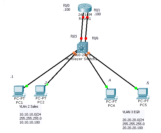
Up till now, only the PC’s in the same VLAN can communicate; in order for the pc from 10.10.10.0/24 network to communicate with other side, we will need a router between them.
So, we add R1 with:
f0/0=10.10.10.100 (act as Default Gateway for VLAN 2)
f0/1 =20.20.20.100 (act as Default Gateway for VLAN 3)
After we assign IP addresses, we will see the following on R1:
R1#show ip int bri
R1#show ip int brief
Interface IP-Address OK? Method Status Protocol
FastEthernet0/0 10.10.10.100 YES manual up up
FastEthernet0/1 20.20.20.100 YES manual up up
Vlan1 unassigned YES unset administratively down down
Now from PC1, we cannot even ping the Default Gateway=10.10.10.100, why? Think of the OSI layer model. Remember IP is at layer 3, here in our topology:
1) first layer is physical – cabling
2) 2nd layer is Data Link – Mac addresses and the switch
3) Third layer is IP – router
As we see from the switch, port f0/3 is not in vlan 2 and port f0/6 is not in VLAN 3.
Here is the VLAN port assignments before the change:
SW1#show vlan brief
| VLAN | Name | Status | Ports |
| 1 | default | active | Fa0/3, Fa0/6, Fa0/7, Fa0/8
Fa0/9, Fa0/10, Fa0/11, Fa0/12 Fa0/13, Fa0/14, Fa0/15, Fa0/16 Fa0/17, Fa0/18, Fa0/19, Fa0/20 Fa0/21, Fa0/22, Fa0/23, Fa0/24 Gig0/1, Gig0/2 |
| 2 | Sales | active | Fa0/1, Fa0/2 |
| 3 | EGR | active | Fa0/4, Fa0/5 |
Now we need to fix it:
SW1#config t
Enter configuration commands, one per line. End with CNTL/Z.
SW1(config)#int f0/3
SW1(config-if)#sw
SW1(config-if)#switchport mo
SW1(config-if)#switchport mode acc
SW1(config-if)#switchport mode access
SW1(config-if)#sw
SW1(config-if)#switchport acc
SW1(config-if)#switchport access vl
SW1(config-if)#switchport access vlan 2
SW1(config-if)#
Now we do the same for f0/6, since we have connected the router int to port f0/6 on the switch.
SW1(config-if)#
SW1(config-if)#
SW1(config-if)#int f0/6
SW1(config-if)#switchport mode access
SW1(config-if)#switchport access vlan 3
SW1(config-if)#
Let’s check the VLAN’s on the switch now:
SW1#show vlan brief
| VLAN | Name | Status | Ports |
| 1 | default | active | Fa0/7, Fa0/8, Fa0/9, Fa0/10
Fa0/11, Fa0/12, Fa0/13, Fa0/14 Fa0/15, Fa0/16, Fa0/17, Fa0/18 Fa0/19, Fa0/20, Fa0/21, Fa0/22 Fa0/23, Fa0/24, Gig0/1, Gig0/2 |
| 2 | Sales | active | Fa0/1, Fa0/2, Fa0/3 |
| 3 | EGR | active | Fa0/4, Fa0/5, Fa0/6 |
Now PC1=10.10.10.1 should ping 20.20.20.4.
[bs_icon name=”glyphicon glyphicon-expand”] Watch the video and you will be able to understand CCNA VLAN Configuration much better and Please subscribe to our YouTube Channel.


Want more information on how to become Cisco CCNA Certified? Learn more!
Join our Cisco CCNA facebook study group!

Also published on Medium.
