

If you’ve already signed up for Amazon Web Services (AWS), you can start using Amazon EC2 immediately. You can open the Amazon EC2 console, click Launch Instance, and follow the steps in the launch wizard to launch your first instance. Read more »
Posted by gol & filed under Amazon AWS.
Amazon Elastic Compute Cloud (Amazon EC2) provides scalable computing capacity in the Amazon Web Services (AWS) cloud. Using Amazon EC2 eliminates your need to invest in hardware up front, so you can develop and deploy applications faster. Read more »
Posted by gol & filed under Cisco CCNA.
Posted by gol & filed under Cisco CCNA.
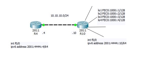
Now I will do small Lab:
R4=10.10.10.4
R10=10.10.10.10 connected via LAN link
Read more »
Posted by gol & filed under Cisco CCNA.
Follow @ASM_Educational
Source Logical Operations
Get our complete tutorial in PDF
Related Links:
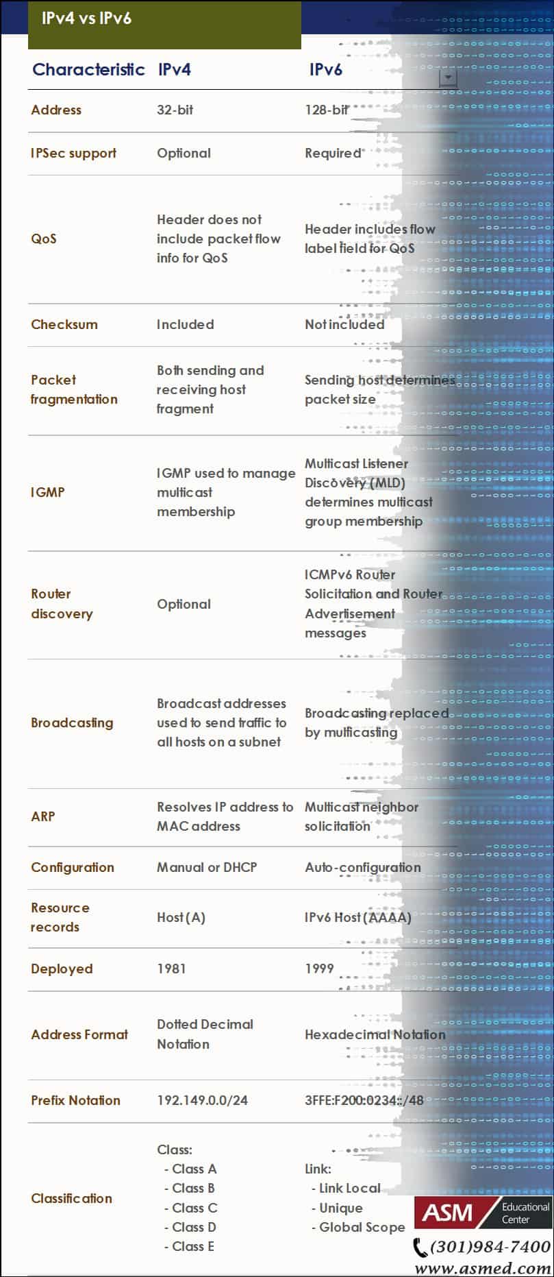
Configuring IPv4
Configuring IPv6
Want more information on how to become Cisco CCNA Certified? Learn more!
Join our Cisco CCNA facebook study group!
Posted by gol & filed under Cisco CCNP.
Follow @ASM_Educational
Source Logical Operations
Get our complete tutorial in PDF
Configuring IPv6
- Overview of IPv6
- Implement IPv6 Addressing
- Implement IPv6 and IPv4
- Transition from IPv4 to IPv6
Posted by gol & filed under Cisco CCNA.
Follow @ASM_Educational
Source Logical Operations
Get our complete tutorial in PDF
Configuring IPv6
- Overview of IPv6
- Implement IPv6 Addressing
- Implement IPv6 and IPv4
- Transition from IPv4 to IPv6
Posted by gol & filed under Cisco CCNA.
Follow @ASM_Educational
Source Logical Operations
Get our complete tutorial in PDF
Configuring IPv4
- Overview of the TCP/IP Protocol Suite
- Describe IPv4 Addressing
- Implement Subnetting and Supernetting
- Configure and Troubleshoot IPv4
Posted by gol & filed under Cisco CCNA.
Description of OSI layers
The recommendation X.200 describes seven layers, labeled 1 to 7. Layer 1 is the lowest layer in this model.
Posted by gol & filed under Cisco CCNA.
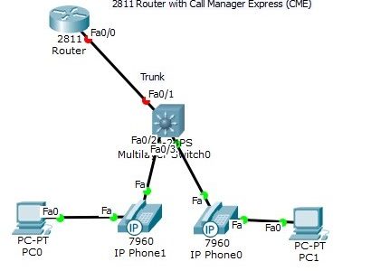
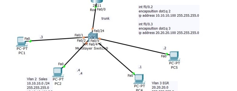
The Trunk port between the router and switch had to be manually configured using sub-interfaces. Note, however, that the DATA vlan traffic and the phone VOICE vlan traffic for each host is carried over the same link (multiple vlan traffic over the same port). Read more »
Posted by gol & filed under Cisco CCNA.
Build the following topology in packet tracer. After testing our configuration, we will deploy on devices.
Read more »
Posted by gol & filed under Cisco CCNA.
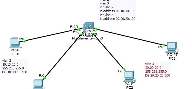
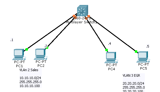
Layer 3 Switch
Now that we have seen how a “router on a stick” works, we can introduce the Layer 3 switch. In the “router on a stick” topology, what if we could bring the router inside the switch? Read more »
Posted by gol & filed under Cisco CCNA.
Using DHCP Server with Inter-Vlan Routing (Router on stick)
On Last Video we talked about the router on stick that is we made sure that client from Network 10.10.10.0 can communicate with Network 20.20.20.0
Posted by gol & filed under Cisco CCNA.
Setting up VLAN’s
On a new switch, all the ports are in VLAN 1 by default. We just plug in the Ethernet cables and the devices can communicate. Furthermore, all the ports are in the up/up (administratively up) mode. Read more »
Posted by gol & filed under CompTIA Linux+.
In order to make troubleshooting as easy as possible, you should always use an organized methodology. Using simple best practices will do just that. Read more »
Posted by gol & filed under CompTIA Linux+.
In order to keep your Linux system running smoothly, it is vital to maintain it properly.
Read more »
Posted by gol & filed under CompTIA Linux+.
As with any other operating system, administration efforts are necessary for any linux system. These include the following tasks: Read more »
Posted by gol & filed under CompTIA Linux+.
Configuring your Xwindows
No matter what desktop environment you chose, it is most likely that it will use the Xwindows architecture. Read more »
Posted by gol & filed under CompTIA Linux+.
Media
Linux installation can be done using a variety of different media. Each installation method has different pros and cons depending on the environment you have. Here are some examples: Read more »
Posted by gol & filed under CompTIA Linux+.
Linux Uses
Linux is a pretty flexible operating system. Although it has got a lot of credibility over the years as a stable server platform, it is also an excellent desktop platform. Databases, mail servers as well as many appliances can be installed. Read more »
Posted by gol & filed under CompTIA Linux+.
Linux is a 32 bit open source operating system. It is based on the very popular Unix operating system and it’s code is freely available (thus explaining the “open source” label as opposed to closed source where the code is not available freely). Read more »
Posted by gol & filed under Amazon AWS.
Amazon Simple Storage Service is storage for the Internet. It is designed to make web-scale computing easier for developers. Read more »
Do You Have What It Takes for a Career in Technology?
Information Technology (IT) has become such a widespread career choice. But few people actually know what IT is and what its discipline entails.
The digital world may tempt you to jump on the information technology wagon. But is it the right choice for you? Talk to one of our advisers and take our IT Assessment Test to see if IT is the right field for you.
I’m new to IT, what certifications are best for me?
Whether you’re a college student looking to advance your career ahead of your peers or from another sector trying to change your career. The Information Technology field offers plenty of opportunities regardless of where your true passion lies. But how can you boost careers — and fast? Not every career needs years to launch. In the tech industry, an education will help — but it isn’t 100 percent necessary. Take for instance the IT field. A handful of entry-level positions in this burgeoning field simply require a certification.
But you may be asking, which IT certification should I get first?
Build your foundation first
If you’re just starting out, you’d want to pursue IT certifications that acquaint you with how to maximize the use of computers, mobile and cloud technology in a business environment first.,
There are certifications that are Ideal for students and professionals who don’t have prior IT experience. These certifications are designed to get students and career changers up to speed on how computers, operating systems and networks function, providing the building blocks of IT.
IT certifications to start your career
CompTIA A+
Your ticket to help desk and technical support jobs. CompTIA A+ shows you know how to troubleshoot common tech problems in corporate environments.
Jobs related to CompTIA A+: Help Desk Technician, Technical Support Specialist, Systems Administrator, IT Technician, IT Assistant
Learn more about our: CompTIA A+ Bootcamp.
The ITIL® 4 Foundation
The ITIL® 4 (version 4) Foundation is the newest entry level Certification Course for IT Service Management Best Practices. It is designed to help businesses manage risks, strengthen customer relations, establish cost-effective practices and build stable IT environments for growth, scale and change.
Jobs related to ITIL 4 Foundation: Process coordinator, Incident Coordinator, Configuration Analyst, Service Desk Level 1, Support Specialist.
Learn more about our: ITIL 4 Bootcamp
IT certifications to explore specialties
CompTIA Network+
Proves your knowledge about managing enterprise networks, solving networking issues, troubleshooting network devices and keeping tabs on network security.
Jobs related to CompTIA Network+: Network Support Specialist, Network Administrator, Systems Administrator, Systems Analyst, Network Engineer
Jobs related to CompTIA Network+: Network Administrator, Network Engineer, Help Desk Support, Service Technician, IT support Specialist
Learn more about our: CompTIA Network+ Bootcamp
CompTIA Security+
Great for tech support and computer networking professionals who want to get into cybersecurity. This certification proves you know how to secure networks, keep digital data confidential and ward off hackers.
Jobs related to CompTIA Security+: Cybersecurity Specialist, Security Administrator
Learn more about our: CompTIA Security+ Bootcamp
AWS Certified Solutions Architect – Associate
Solutions architects optimize the use of the AWS Cloud by understanding AWS services and how these services fit into cloud-based solutions. This certification is a great introduction to cloud computing.
Jobs related to AWS Certified Solution Architect – Associate: Cloud Architect, Cloud Engineer, Operational Support Engineer, Cloud Software Engineer, System Integrator — Cloud
Learn more about our: AWS Certified Solution Architect – Associate Bootcamp
Whether you’re a college student or a professional who wants to change a career, IT certifications shows employers that you have what it takes and have the skills needed for the IT roles in their organizations.
College students can also avail a federally funded scholarship for your certifications. Learn more
Posted by admin & filed under CompTIA A+, MICROSOFT MTA O/S.
Security Settings
CompTIA A+ Exam objectives 2.6
(Compare and contrast the differences of basic Microsoft Windows OS security settings)
User and Groups
There are different levels of user accounts built into the Windows operating system. There are administrators, guests, and standard users. An administrator is the super-user of the Windows operating system. If you have administrative rights, then you effectively can control everything about the operating system.
There are also guest users in the Windows operating system. These guest users are disabled by default. But if you do enable the guest user, they will have limited access to the operating system. The majority of people that log in to Windows are standard users. These are people that are browsing the internet or working on spreadsheets or word processing documents. A standard user does not have full and complete access to the operating system, but they are able to use the operating system to perform day-to-day tasks.
There are also groups built into Windows. Some of these groups can be created to assign rights and permissions to others, and other groups are built into the operating system. A good example of this is the power users group that provides additional rights and permissions to a standard user without giving them all of the permissions that may be assigned to an administrator. When you access a file in the Windows operating system, your access to that file may be controlled through NTFS permissions or share permissions.
NTFS vs. Share Permissions
NTFS permissions are permissions assigned to the file system itself. This means if you’re accessing a file locally on the computer, the NTFS permissions will apply. And if you’re accessing that file across the network using a share, these NTFS permissions will also apply to you as well. There is a separate group of permissions that are associated with users connecting across a share. This means you can have one set of permissions for people who are accessing this file locally and a completely different set of permissions for somebody accessing it across the network.
As you can imagine, this could create a conflict. What if the NTFS permission is set to deny access, but the share permission is set to allow access? Whenever you have that type of conflict, the most restrictive setting will win, which means if the deny is set on this file on either one of those permissions, then they deny will beat that allow permission that may be somewhere else. NTFS permissions are inherited from parent objects in the file system, which means you don’t have to manually assign NTFS permissions to every single file. It will simply use the permissions assigned to the parent object.
If you move that file to a different volume, then the permissions will be associated with where you put it on that volume. If you move that file within the same volume, there is simply a pointer that’s changed in the file system, which means it will keep the permissions if you’re moving it within the same volume. In this view, we’re looking at two different sets of permissions that are pointing to the same folder. This would be the folder under Users, Professor, Documents, and Reports.
You can see there may be NTFS permissions that provide full access to this particular folder. But if you were to look at the share permissions, anybody connecting across the network would only have read access to this particular folder. There are a number of shares that are created automatically by the operating system during the installation process. These are administrative shares, and most of these shares are hidden from view.
For example, any share that has a dollar sign at the end of it is automatically hidden by the operating system. So a share that had a C$ would be the share for the entire C drive, but it would be hidden by other people that are connecting to the system. Another good example of administrative shares are the ADMIN$ share and the PRINT$ share. If you wanted to view the shares available on your system, you can go to the command line and use the net share command to list out all the share names and the resources associated with that share.
Shared Files and Folders
We mentioned earlier that permissions associated with a file in the file system can have all of those permissions inherited from a parent object. If you were to manually change the permissions for that file in the file system, those permissions would be called explicit permissions. Here’s an example of inherited permissions. Here’s a music folder on my Windows computer. And you can see there are a number of folders underneath the Music folder. This means that the Music folder would have the parent permissions, and the folders underneath the Music folder would have the child permissions.
If we were to set permissions on the Music folder to allow access, we won’t have to go to each individual folder to also allow access, because all of those permissions will be inherited from the parent object. If we configured the Music folder to provide access, then access to all of the child folders would also be allowed, because those permissions are inherited from the parent object. We can override these inherited permissions by changing the permissions ourselves. And when we change them, they would be explicit permissions.
Let’s take the example of our music folder. If we set up a deny permission to our music folder, then that particular set of permissions would be inherited by all of the child objects. But there may be a child folder that we would like to provide access to others, and we can explicitly define what folder we would like to assign. So even though all of the other permissions were inherited, we can specify our own permissions, and those would be explicit permissions.
Learn more about our CompTIA A+ Certification
Credits: Professor Messor
Posted by admin & filed under CompTIA A+, MICROSOFT MTA O/S.
System Utilities
CompTIA A+ Exam objectives 1.5
(Given a scenario, use Microsoft operating system features and tools.)
What are system utilities?
Utility programs are designed to carry out specific tasks. The tasks to be carried out are not typically performed by the operating system as part of its day to day operating of the system. Utility programs are designed for more specific purposes. Common examples of utility software include anti-virus software, disk defragmenters and system restoration.
Here is a picture example of some utilities, some of these will be covered, but there are some more important ones that will be explained for this lesson.
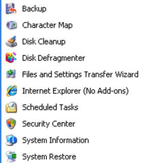
Here are the 12 system utilities needed for the A+ exam:
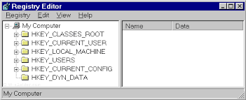
REGEDIT
The Windows Registry serves as an archive for collecting and storing the configuration settings of Windows components, installed hardware/software/application and more. A Windows component, hardware or a software, retrieves the registry entries or keys relating to it, every time it is started. It also modifies the registry entries or keys corresponding to it, in its course of execution. When keys are added to the registry, the data are sorted as computer-specific data or user-specific data in order to support multiple users.
The Regedit command launches regedit.exe
COMMAND
This command launches a standard command prompt for the user.
Services.msc
This command in the command console launches the services console.
MMC
MMC is a centralized data base that contains many tools which are typically scattered, and brings them all together so that the user may select which ones are needed.
MSTSC
This program allows a PC connected by a remote desktop sessions to be able to edit the config files of different PCs using the RDP.
NOTEPAD
Notepad is a secure and reliable text editor in Windows.
EXPLORER
Explorer is Window’s file management system. It does many actions, such as creating, copying and renaming files and folders.
MSINFO32
Essentially launches system information. Windows says this :
You can use the MSINFO32 command-line tool switches to do all of the following:
- Use System Information from a batch file
- Create .nfo or .txt files that contain information from specified categories.
- Open System Information and display only specific categories.
- Save a file silently (without opening System Information).
- Start System Information connected to a remote computer.
- Create a shortcut that opens System Information in a frequently-used configuration.
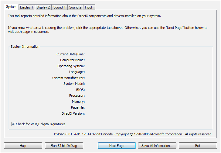
DxDiag
This tool can be used to collect information about DirectX sound and video. Can help for troubleshooting a problem.
Disk Defragmenter
Rearranges the file fragments on a disk into contiguous clusters to be able to read them faster.
System Restore
This utility can create system images, and then restores the system when asked by user.
Windows Update
Can be used to manage software and security issues, and allows microsoft to fix them quickly and uniformly.
Learn more about our CompTIA A+ Certification
Credits: HN Computing , Comodo , CertBlaster , Windows Help
Posted by admin & filed under CompTIA A+, MICROSOFT MTA O/S.
Server Roles
CompTIA A+ Exam objectives 2.5
(Summarize the properties and purposes of services provided by networked hosts.)
What do server roles achieve?
Server roles allow there to be more convenient or efficient options of doing specific tasks, such as accessing the internet, or using the printer.
Here are the 9 different types covered by CompTIA:
Web server
At the most basic level, whenever a browser needs a file which is hosted on a web server, the browser requests the file via HTTP. When the request reaches the correct web server (hardware), the HTTP server (software) accepts the request, finds the requested document (if it doesn’t then a 404 response is returned), and then sends it back to the browser, also through HTTP.

File server
A high-speed computer in a network that stores the programs and data files shared by it’s users. It acts like a remote disk drive. The difference between a file server and an application server is that the file server stores the programs and data, while the application server runs the programs and processes the data.
Print server
A computer in a network that controls one or more printers. The function is typically part of the operating system but may be an add-on utility that stores the print-image output from users’ machines and feeds it to the printer one job at a time. The computer and its printers are known as a “print server” or a file server with “print services.”
DHCP server
Dynamic Host Configuration Protocol (DHCP) is a network protocol that enables a server to automatically assign an IP address to a computer from a defined range of numbers (that is, a scope) configured for a given network.
DNS server
A dedicated server or a service within a server that provides DNS name resolution in an IP network. It turns names for websites and network resources into numeric IP addresses. DNS servers are used in large companies, in all ISPs and within the DNS system in the Internet, a vital service that keeps the Internet working. They are set up by network administrators and typically do not exist in the very small business or home.
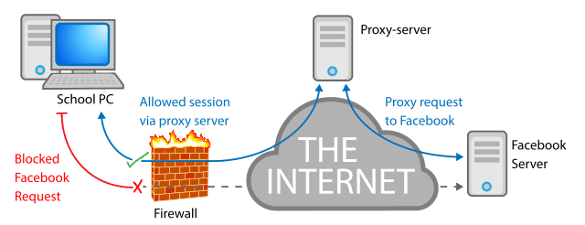
Proxy server
A proxy server, also known as a “proxy” or “application-level gateway”, is a computer that acts as a gateway between a local network (for example, all the computers at one company or in one building) and a larger-scale network such as the internet. Proxy servers provide increased performance and security.
A proxy server works by intercepting connections between sender and receiver. All incoming data enters through one port and is forwarded to the rest of the network via another port. By blocking direct access between two networks, proxy servers make it much more difficult for hackers to get internal addresses and details of a private network.
Mail server
A mail server (or email server) is a computer system that sends and receives email. In many cases, web servers and mail servers are combined in a single machine.
Authentication server
A device used in network access control. An authentication server stores the usernames and passwords that identify the clients logging in, or it may hold the algorithms for token access. For access to specific network resources, the server may itself store user permissions and company policies or provide access to directories that contain the information.
syslog
A protocol for transmitting event messages and alerts across an IP network. Messages are sent by the operating system or application at the start or end of a process or to report the current status of a process. Initially developed for the Unix sendmail application, syslog became commonly used in all environments and was made an IETF standard in 2001.
Learn more about our CompTIA A+ Certification
Posted by admin & filed under CompTIA A+, MICROSOFT MTA O/S.
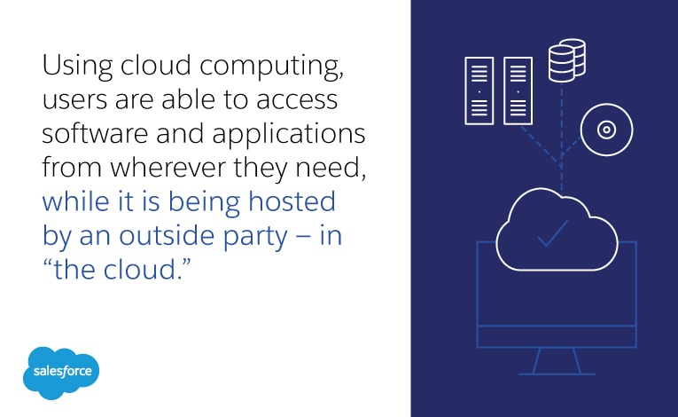
Introduction to Cloud Computing
Simply put, cloud computing is the delivery of computing services—including servers, storage, databases, networking, software, analytics, and intelligence—over the Internet (“the cloud”) to offer faster innovation, flexible resources, and economies of scale. You typically pay only for cloud services you use, helping you lower your operating costs, run your infrastructure more efficiently, and scale as your business needs change.
The Common Cloud Models
There are three different types of cloud models, and each has their own advantages and disadvantages. The cloud model that the user would use depends on what they need.
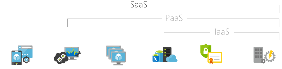
IaaS
SaaS
PaaS
Infrastructure as a Service
Software as a Service
Platform as a Service
Infrastructure as a Service, sometimes abbreviated as IaaS, contains the basic building blocks for cloud IT and typically provide access to networking features, computers (virtual or on dedicated hardware), and data storage space. Infrastructure as a Service provides you with the highest level of flexibility and management control over your IT resources and is most similar to existing IT resources that many IT departments and developers are familiar with today.
Software as a Service provides you with a completed product that is run and managed by the service provider. In most cases, people referring to Software as a Service are referring to end-user applications. With a SaaS offering you do not have to think about how the service is maintained or how the underlying infrastructure is managed; you only need to think about how you will use that particular piece software. A common example of a SaaS application is web-based email where you can send and receive email without having to manage feature additions to the email product or maintaining the servers and operating systems that the email program is running on.
Platforms as a service remove the need for organizations to manage the underlying infrastructure (usually hardware and operating systems) and allow you to focus on the deployment and management of your applications. This helps you be more efficient as you don’t need to worry about resource procurement, capacity planning, software maintenance, patching, or any of the other undifferentiated heavy lifting involved in running your application.
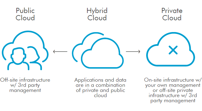
Cloud Computing Deployment Models
Public
-
It may be owned, managed, and operated by a business, academic, or government organization, or some combination of them.
-
Services are delivered over a network which is open for public usage.
Private
-
Exclusive user by a single organization comprising multiple consumers (e.g. business units).
-
The platform for cloud computing is implemented on a cloud-based secure environment that is safeguarded by a firewall which is under the governance of the IT department that belongs to the particular customer.
Hybrid
- The cloud infrastructure is a composition of two or more distinct cloud infrastructures (private,community, or public) that remains unique entities, but are bound together by standardized or proprietary technology that enables data and application portability.
Community
-
Provisioned for exclusive user by a specific community of consumers from organizations that have shared concerns.
-
It may be owned, managed, and operated by one or more of the organizations in the community, a third party, or some combination of them and it may exist on or off premises.
-
The setup is mutually shared between many organizations that belong to a particular community.
Credits: Microsoft Azure ,Amazon AWS, U.S DOI, Salesforce
Posted by Ajmal Ward & filed under CompTIA Security+, MICROSOFT MTA SECURITY.
Major Security Breaches of 2024: What You Need to Know
1. LastPass Breach (2024)
Date of Discovery: January 2024
In early 2024, LastPass, one of the leading password management platforms, suffered another breach, following a significant incident in 2022. Hackers infiltrated user vaults, gaining access to encrypted data. While the data remains encrypted, this breach raised concerns about the overall safety of sensitive information stored in password managers.
Impact:
- Encrypted user data compromised, including passwords.
- Users were urged to update master passwords and enable multi-factor authentication (MFA).
2. T-Mobile Data Breach (2024)
Date of Discovery: March 2024
T-Mobile experienced a significant data breach in March, affecting millions of customers. Cybercriminals accessed personal customer data, including phone numbers and billing information, through unauthorized access to the network.
Impact:
- Over 40 million customers affected.
- Exposure of personal details, but no financial data was compromised.
3. U.S. Health Insurance Data Breach (2024)
Date of Discovery: April 2024
A major U.S. health insurance provider reported a breach that exposed millions of customers’ personal health data. The breach occurred after hackers gained unauthorized access to sensitive medical and insurance information stored within the company’s system.
Impact:
- Over 30 million individuals affected.
- Exposed medical records, insurance information, and personal health data.
4. Microsoft Exchange Server Vulnerability Exploited (2024)
Date of Discovery: May 2024
Cybercriminals took advantage of a vulnerability in Microsoft Exchange Server, gaining unauthorized access to emails and sensitive company data. Although patches were rolled out quickly, many organizations were impacted before they had a chance to update their systems.
Impact:
- Thousands of organizations worldwide affected.
- Critical company data, including emails, exposed.
5. Volkswagen Group of America (VWoA) Data Breach (2024)
Date of Discovery: June 2024
Volkswagen’s U.S. division experienced a data breach in June, exposing millions of customer records. The breach involved unauthorized access to a system that stored sensitive information such as vehicle details, customer names, and addresses.
Impact:
- More than 3 million customer records compromised.
- Affected customers were notified and offered identity protection services.
6. UK’s National Health Service (NHS) Data Breach (2024)
Date of Discovery: July 2024
In July, the NHS reported a breach that compromised patient records via an external partner’s network. This breach exposed confidential medical records, and the stolen data raised concerns about privacy in healthcare systems.
Impact:
- Over 2 million patient records exposed.
- Ongoing efforts to secure patient data and prevent future breaches.
7. Twitter Data Breach (2024)
Date of Discovery: August 2024
A Twitter data breach in August involved hackers exploiting vulnerabilities in Twitter’s API to gain access to personal user information, including phone numbers and email addresses.
Impact:
- Affected over 200 million users.
- Personal details, including phone numbers and email addresses, exposed.
8. Uber Data Breach (2024)
Date of Discovery: September 2024
Uber was hit by a ransomware attack that targeted internal company data. This attack compromised sensitive business information, employee data, and customer details. The breach is believed to have been orchestrated by a hacker group with ties to larger cybercrime syndicates.
Impact:
- Exposed sensitive business data, including financial and customer information.
- Uber worked quickly to contain the breach and strengthen its cybersecurity measures.
9. Ransomware Attack on U.S. Schools (2024)
Date of Discovery: October 2024
A coordinated ransomware attack affected multiple U.S. school districts, disrupting online learning and encrypting educational systems. The attack forced many schools to shut down temporarily, affecting hundreds of thousands of students.
Impact:
- More than 500,000 students were affected by data loss and service disruption.
- Several districts opted not to pay the ransom, instead focusing on rebuilding and strengthening defenses.
10. Australian Broadcasting Corporation (ABC) Breach (2024)
Date of Discovery: November 2024
ABC in Australia suffered a significant data breach involving its internal systems, where hackers accessed sensitive documents and media plans. It’s believed the attackers may have had political motivations linked to espionage.
Impact:
- Exposure of internal documents, including media strategies and unbroadcasted stories.
- ABC has implemented further security measures to protect its data.
Are you looking to break into the exciting field of Cybersecurity? Join our 5-day CompTIA Security+ Boot camp Training and build your Cybersecurity knowledge and skills.
Posted by Ajmal Ward & filed under CompTIA Security+, MICROSOFT MTA SECURITY.
What's New in the Latest Version of CompTIA Security+ (SY0-701)?
The CompTIA Security+ certification has received a major refresh with the new SY0-701 version, reflecting the latest trends in cybersecurity. Here’s a quick look at what’s new:
- Cloud and Hybrid Security: Greater focus on securing cloud and hybrid environments, ensuring professionals can manage modern infrastructures.
- Threat Intelligence: Expanded coverage on threat intelligence, helping organizations anticipate and counter potential attacks.
- Advanced Security Architectures: Introduction to advanced frameworks like Zero Trust, emphasizing secure design and implementation.
- Automation & AI: Increased emphasis on automation and AI in security operations, from threat detection to ethical considerations.
- Governance, Risk, and Compliance: Strengthened focus on risk management, legal issues, and compliance frameworks.
- Incident Response & Forensics: Expanded scenarios for incident response and digital forensics, equipping professionals to handle breaches effectively.
- Secure Development: More coverage on secure coding practices and DevSecOps, integrating security throughout the software lifecycle.
This update ensures that Security+ certified professionals stay current with today’s cybersecurity challenges. Ready to take your skills to the next level? Dive into the new CompTIA Security+ SY0-701!

Are you looking to break into the exciting field of Cybersecurity? Join our 5-day CompTIA Security+ Boot camp Training and build your Cybersecurity knowledge and skills.
Posted by Ajmal Ward & filed under CompTIA Security+, MICROSOFT MTA SECURITY.
Why Spam is a Major Security Concern and How to Protect Yourself
Spam emails are a persistent nuisance that clog up our inboxes and waste our time, but they are much more than just an annoyance. Spam is a significant security concern that can pose a threat to individuals and organizations alike. In this blog, we will explore why spam is a security concern and provide some tips on how to protect yourself from spam.
How to Protect Yourself from Spam?
Use Spam Filters: Most email services and clients offer spam filters that can be used to automatically filter out unwanted and potentially dangerous emails. Make sure that your email provider has a robust spam filter and that you have it turned on.
Don’t Click on Links or Attachments: Be cautious when opening emails from unknown or suspicious senders, and avoid clicking on links or downloading attachments. If you are unsure about the authenticity of an email, verify it with the sender before opening any links or attachments.
Use Anti-Virus Software: Install reputable anti-virus software on your device and keep it updated to protect against malware and other threats.
Be Careful with Personal Information: Do not share personal information such as passwords or financial information in response to unsolicited emails or requests. Always verify the legitimacy of the request before sharing any personal information.
Educate Yourself: Stay informed about the latest spam and phishing trends and tactics, and educate yourself on how to identify and avoid them.
In conclusion, spam is a serious security concern that should not be taken lightly. By following these best practices and staying vigilant, you can protect yourself from spam and the threats it poses. Remember, when it comes to spam, prevention is always better than cure.
Posted by Ajmal Ward & filed under CompTIA Security+, MICROSOFT MTA SECURITY.
Understanding Trust in Information Security
As technology continues to evolve and the reliance on digital systems and networks increases, trust has become a crucial aspect of information security. Establishing and maintaining trust is essential in protecting sensitive data, ensuring the integrity of systems, and mitigating security risks. In this comprehensive guide, we will delve into the concept of trust in the context of CompTIA Security+ certification and explore its key components and implications.
Authentication: The Foundation of Trust
At the heart of trust in information security is authentication, the process of verifying the identity of a user, device, or system. Authentication methods can include something a user knows, something a user has, or something a user is. We will explore various authentication methods, such as passwords, smart cards, and biometric recognition, and discuss best practices for implementing strong authentication mechanisms.
Authorization: Determining Access Rights
Once a user, device, or system has been authenticated, authorization comes into play. Authorization determines what actions or resources an authenticated entity is allowed to access. We will delve into the concept of authorization, including role-based access control (RBAC) and other authorization models, and discuss how to implement effective authorization mechanisms to prevent unauthorized access and data breaches.
Trust Models: Establishing Trust Relationships
Trust models are frameworks used to establish and manage trust between different entities in a system or network. We will explore common trust models, such as single sign-on (SSO) frameworks, multi-factor authentication (MFA) systems, and public key infrastructure (PKI) implementations. We will discuss their strengths, weaknesses, and best practices for implementation to ensure secure and trusted interactions between entities.
Trust Boundaries: Managing Interfaces
Trust boundaries are the points or interfaces where different levels of trust meet or interact. Managing trust boundaries is crucial in preventing security breaches and ensuring the integrity of systems and networks. We will discuss how to identify and manage trust boundaries, including considerations for physical and logical boundaries, and best practices for securing these critical points of interaction.
Trustworthiness: Ensuring Reliability and Security
Trustworthiness is the overall reliability, integrity, and security of a system or network. It involves implementing appropriate security controls, maintaining system updates and patches, and following best practices for securing data, systems, and networks. We will explore the concept of trustworthiness and discuss how to implement measures to ensure the trustworthiness of information systems and networks.
Conclusion: Trust as a Pillar of Information Security
In conclusion, trust is a foundational concept in information security and plays a critical role in protecting sensitive data, systems, and networks. Understanding and managing trust is essential for information security professionals and is a key topic covered in the CompTIA Security+ certification exam. By comprehensively understanding the components of trust, including authentication, authorization, trust models, trust boundaries, and trustworthiness, information security practitioners can effectively mitigate security risks and safeguard valuable information assets.
Whether you are a security professional preparing for the Security+ certification exam or an IT practitioner looking to enhance your knowledge of information security, this comprehensive guide on understanding trust in information security will provide valuable insights and practical recommendations for establishing and maintaining trust in today’s complex digital landscape. Trust is a critical pillar of information security, and mastering its concepts is essential for protecting against security threats and ensuring the confidentiality, integrity, and availability of information and resources.
Posted by Ajmal Ward & filed under CompTIA Security+, MICROSOFT MTA SECURITY.
Identity fraud
Identity fraud, also known as identity theft, is a serious crime that can have devastating consequences for individuals and businesses alike. With the increasing digitization of our lives and the proliferation of personal information online, the risk of falling victim to identity fraud is higher than ever. In this blog, we will delve into what identity fraud is, the risks associated with it, and steps you can take to protect yourself.

What is Identity Fraud?
Identity fraud occurs when someone steals your personal information and uses it without your consent to commit fraudulent activities, such as making unauthorized purchases, opening bank accounts or credit cards, filing false tax returns, or even committing crimes in your name. Personal information that can be used for identity fraud includes your name, address, social security number, date of birth, phone number, email address, financial account numbers, and more.
The Risks of Identity Fraud
The risks of identity fraud are numerous and can have serious consequences for victims. Some of the risks associated with identity fraud include:
- Financial Losses: Identity thieves can drain your bank accounts, make fraudulent purchases using your credit cards, and even open new credit accounts in your name, leaving you with significant financial losses and damage to your credit score.
- Legal Troubles: If an identity thief commits crimes using your personal information, you may find yourself facing legal troubles, including being wrongly accused of criminal activities.
- Emotional Distress: Discovering that your personal information has been stolen and misused can be emotionally distressing, causing anxiety, stress, and a sense of violation.
- Time and Effort to Resolve: Resolving the aftermath of identity fraud can be time-consuming and require significant effort, including contacting financial institutions, credit bureaus, and law enforcement agencies, filling out paperwork, and dealing with the bureaucratic process.
Protecting Yourself from Identity Fraud
While identity fraud can be a serious threat, there are steps you can take to protect yourself and reduce your risk of falling victim to this crime. Here are some important measures you can implement:
- Safeguard Your Personal Information: Be cautious about sharing your personal information online, and only provide it to trusted sources. Avoid sharing sensitive information on social media platforms, and be cautious about the information you share over the phone or via email.
- Use Strong and Unique Passwords: Use strong, unique passwords for all your online accounts, and avoid using common passwords or reusing passwords across different accounts. Consider using a password manager to help you generate and store complex passwords securely.
- Monitor Your Financial Accounts: Regularly monitor your bank and credit card accounts for any unauthorized transactions or suspicious activity. Report any discrepancies immediately to your financial institution.
- Be Cautious of Phishing Attempts: Be wary of emails, phone calls, or text messages that request your personal information or financial details. Be cautious of clicking on links or downloading attachments from unknown sources, and verify the legitimacy of any communication before providing any sensitive information.
- Secure Your Devices: Keep your devices, including your computer, smartphone, and tablet, secure with up-to-date antivirus software, firewalls, and security patches. Avoid using public Wi-Fi networks for sensitive transactions and be cautious of downloading apps or software from unknown sources.
- Check Your Credit Reports: Regularly review your credit reports from the major credit bureaus (Equifax, Experian, and TransUnion) to check for any suspicious activity or inaccuracies. You are entitled to a free credit report from each bureau every year.
- Consider Identity Theft Protection Services: Consider enrolling in an identity theft protection service that offers monitoring, alerts, and assistance in case of identity fraud. Do your research and choose a reputable service with good reviews.
Conclusion
In conclusion, identity fraud is a serious crime that can have severe consequences for individuals and businesses. With the increasing digital landscape and the proliferation of personal information online, it’s crucial to take steps to protect yourself from falling victim to identity fraud. By safeguarding your personal information, using strong and unique passwords, monitoring your financial accounts, being cautious of phishing attempts, securing your devices, checking your credit reports, and considering identity theft protection services, you can significantly reduce your risk of identity fraud. Stay vigilant, be cautious, and take proactive measures to protect your personal information and financial well-being. Remember, prevention is key when it comes to identity fraud, and taking action now can save you from potential devastating consequences in the future.
Posted by Ajmal Ward & filed under CompTIA Security+, MICROSOFT MTA SECURITY.
Whaling
Phishing attacks, a form of cyber attack where malicious actors trick individuals into revealing sensitive information, have become increasingly sophisticated in recent years. One type of phishing attack that has gained prominence is “whaling,” which targets high-level executives and individuals with access to valuable data or funds. Whaling attacks are highly targeted and personalized, making them difficult to detect and defend against. In this blog, we will explore the concept of whaling, the risks it poses to organizations, and how the implementation of security measures, such as Security+, can help protect against this advanced form of phishing.
Understanding Whaling:
Whaling, also known as CEO fraud or business email compromise (BEC), is a type of phishing attack that focuses on high-profile individuals, such as CEOs, CFOs, and other executives. Unlike traditional phishing attacks, which may cast a wide net and target a large number of individuals, whaling attacks are carefully crafted and highly targeted. Cybercriminals conduct thorough research on their victims, gathering information from publicly available sources, social media, and other online platforms to create a convincing facade. They then use this information to send fraudulent emails that appear to be from a trusted source, often posing as a high-ranking executive or a trusted business partner, in order to trick the victim into taking a specific action, such as transferring funds or revealing sensitive information.
Risks of Whaling:
Whaling attacks pose significant risks to organizations, as they can result in financial losses, reputational damage, and data breaches. High-level executives and individuals with access to critical data or financial resources are prime targets for whaling attacks, as their actions can have a significant impact on the organization. Whaling attacks often exploit the human element of cybersecurity, relying on social engineering techniques to manipulate victims into taking actions that may compromise security. The personalized and convincing nature of whaling attacks makes them difficult to detect using traditional security measures, and organizations need to implement specialized security measures to effectively mitigate the risks.
Whaling Security+:
Security+ is a well-known and widely used certification offered by CompTIA, which focuses on information security and validates the skills and knowledge required to secure IT systems and networks. Implementing Security+ best practices can help organizations protect against whaling attacks by enhancing email security, strengthening authentication methods, and providing employee training on identifying and responding to whaling attempts. Some key Security+ practices that can be applied to mitigate whaling risks include:
- Email Authentication: Implementing technologies such as Domain-based Message Authentication, Reporting, and Conformance (DMARC), Sender Policy Framework (SPF), and DomainKeys Identified Mail (DKIM) can help verify the authenticity of incoming emails and detect spoofed or fraudulent emails.
- Employee Training: Providing regular and comprehensive training to employees, especially high-level executives and individuals with access to sensitive data, on identifying and responding to whaling attempts can help increase awareness and reduce the likelihood of falling victim to such attacks.
- Access Control: Implementing strong access control measures, such as multi-factor authentication (MFA), to limit access to critical systems and data can help prevent unauthorized access in case of a successful whaling attack.
- Incident Response: Establishing a robust incident response plan that includes procedures for detecting, reporting, and responding to whaling attacks can help organizations quickly mitigate the impact of a successful attack and prevent further damage.
Conclusion
Whaling attacks pose significant risks to organizations, and it is crucial to implement effective security measures to protect against this advanced form of phishing. Security+, with its focus on information security, can provide organizations with the necessary skills and knowledge to strengthen their defenses against whaling attacks. By implementing email authentication, providing employee training, enforcing access controls, and establishing incident response plans
Posted by Ajmal Ward & filed under CompTIA Security+, MICROSOFT MTA SECURITY.
FREE ISC2 Certified in Cybersecurity Exam Voucher
Did you know that you can use this FREE exam codes to register for ISC2 Certified in Cybersecurity℠ – CC
See www.asmed.com/s1
Are you passionate about technology and interested in a career that offers limitless opportunities? You don’t need prior experience to start your journey in cybersecurity—just the drive to learn and succeed. With the global demand for cybersecurity professionals at an all-time high, now is the perfect time to explore this exciting and rewarding field.
Why Cybersecurity?
Cybersecurity is more than just a job; it’s a mission to protect data, systems, and people from digital threats. As technology evolves, so does the need for skilled professionals who can safeguard our interconnected world. By joining the cybersecurity workforce, you’re not only securing your future but also contributing to the safety and security of countless organizations and individuals worldwide.
ISC2's Commitment to Closing the Cybersecurity Workforce Gap
In an effort to close the cybersecurity workforce gap and bring more diversity into the field, ISC2 is offering a groundbreaking opportunity: FREE Certified in Cybersecurity (CC) Online Self-Paced Training and exams for one million people. This initiative is designed to empower individuals from all backgrounds to kickstart their cybersecurity careers and become part of the world’s largest association of certified cybersecurity professionals.
How to Start Your Journey
Participating in the One Million Certified in Cybersecurity program is simple. Here’s how you can get started:
- Create an Account: If you don’t already have an ISC2 account, you’ll need to create one. If you’re already a member, simply sign in.
- Complete Your Application: Fill out the ISC2 Candidate application form and select “Certified in Cybersecurity” as your certification of interest.
- Access Your Training: Once your application is complete, you’ll become an ISC2 Candidate. This status gives you access to the Official ISC2 Certified in Cybersecurity Online Self-Paced Training and allows you to register for the free certification exam. Access all your resources on the Candidate Benefits page.
- Take the Exam: After completing the training, take the certification exam. Upon passing, you’ll need to complete an application form and pay a U.S. $50 Annual Maintenance Fee (AMF).
- Become Certified: Once you pass the exam and complete all the required steps, you’ll become a certified member of ISC2. As a member, you’ll join the world’s largest association of certified cybersecurity professionals and gain access to a wealth of professional development resources to support your career growth.
Ready to Get Started?
Don’t miss this unique opportunity to break into the cybersecurity field with the support of ISC2. Whether you’re looking to make a career change or advance your current skills, this program provides everything you need to succeed.

Posted by Ajmal Ward & filed under CompTIA Security+, MICROSOFT MTA SECURITY.
How to prepare for CompTIA Network + Job?


Posted by Ajmal Ward & filed under Amazon AWS.
FREE AWS Exam Retake codes
Looking to advance your career and validate your skills? Get AWS Certified and stand out from other professionals with a recognized credential. Boost your confidence with an extra exam retake opportunity (AWPR9A223835), available only with Pearson VUE. Take advantage of this limited-time promotion to schedule and complete your exam between March 15 and May 31, 2023. If you need it, you’ll receive a free retake when you schedule and complete your exam on or before August 1, 2023
To get started:
Click on image or follow the link end of the page:
- Login or create an AWS training account
- Register for your exam
- Apply the promo code during checkout to qualify for a free exam retake
- Validate your skills and show your professional network that you stand out from other professionals.
Follow the link: https://home.pearsonvue.com/AWS/free-retake
Posted by Ajmal Ward & filed under CompTIA Network+, MICROSOFT MTA NETWORKING.
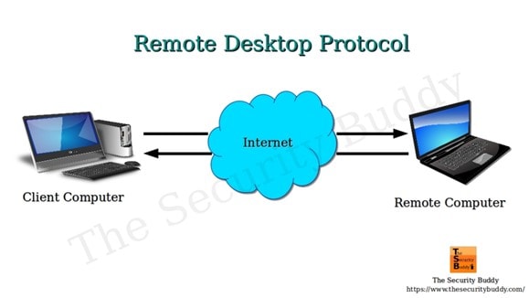
Remote Desktop Protocol (RDP)
RDP is a Microsoft-designed technology that allows two computers to share a GUI using a network connection.
RDP is a proprietary technology initially built by Microsoft that allows two computers to exchange a graphical user interface (GUI) using a standardized network connection. This article explains the meaning of RDP, how it works, its benefits, and the challenges to consider.
What Is Remote Desktop Protocol?
Remote work has existed for quite a while but has recently been brought to the limelight. The COVID-19 pandemic highlighted how much employees could complete from the comfort of their homes. But it also showed the limitations of remote work and its risk for the business. One of those limitations and risks is the need to duplicate the office environment at home, including sensitive files, documents, subscribed applications, etc.
An employee that works with sensitive information might be limited from working remotely even when there is little alternative. This is where the Remote Desktop Protocol (RDP) comes into the scene.
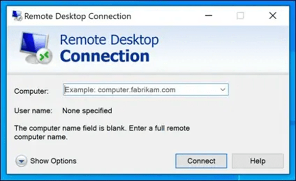
Remote Desktop Protocol is a safe protocol for communication between computer networks. It is an exclusive protocol built by Microsoft that furnishes the user on one desktop with a graphical user interface that they can use to connect with another computer over a network connection directly. For this to work, the user must have the RDP software installed on his computer from which he accesses the other computer running the RDP server.
The Remote Desktop Protocol connection is a tool that allows users to connect to another windows or PC in another location over the internet. The user located far away will be able to log in to the home PC, view the desktop and access the files stored in it, and use the peripheral devices like the mouse and keyboard to control the office PC, just as though they were in front of it.
The Remote Desktop Protocol is not just a tool for remote workers to access their office desktops; it is also invaluable to network admins as they can diagnose and fix non-structural system malfunction without being physically present. Remote employees, those in transit, at a conference, support technicians, and network administrators can use RDP for regular maintenance.
Microsoft developed RDP, but it can link different types of computers. The client that is the PC, the user is logged into can run on multiple operating systems like Windows, macOS, Unix, and Android. At the same time, the server is built for specific operating systems, majorly Windows.
How Does Remote Desktop Protocol Work?
The working principle of the RDP is quite simple and uncomplicated. Like other Remote Desktop software, RDP gives you remote control over another system. However, RDP is the most common protocol used for this purpose.
How does RDP work?
Anything you will control remotely, be it an object or, in this case, a computer system, must be able to receive some signal. Take, for instance, drones. For a drone to move in a direction or change course, it must receive radio signals from the drone controller in the hands of the pilot. Remote Desktop Protocol works by a similar yet different mechanism, but first, we must understand what the client and server represent in the RDP network.
- Server: The server, otherwise known as the host, is the computer you want to connect to and is accessible from any location. It requires the RDP software to be installed on it.
- Client: The client is the remote computer operated by the user who has the authorization to connect to and control the host desktop remotely.
When using Remote Desktop Protocol, signals are sent over the internet rather than radio waves. These signals include input signals from the keyboard and mouse and output display signals from the server. RDP opens a particular channel through the Transmission Control Protocol (TCP or TCP/IP) and sends the information packets in an encrypted format to improve the network’s security. Currently, RDP uses the network port 3389 to transfer all data related to Remote Desktop access.
Before sending the information to the host, the transport driver is in charge of packaging the data. From there, Microsoft communications services direct it to the Remote Desktop ppl to COL prepared channel where the operating system encrypts it and is transmitted.
Encrypting and transmitting data to the host computer over the internet and receiving the desktop display at every point can cause delays in use. Therefore, RDP requires fast internet services to adequately handle the workload while creating a pleasant experience for the user.
When using Remote Desktop access, it is possible to add extra transport drivers for other network protocols depending on peripheral users’ demand to connect to the host computer. This level of independence in the TCP/zip stack improves the performance of RDP and makes it an extensible network.
Properties of the Remote Desktop Protocol
The working principle of RDP is reflected in its properties. These include smart card verification, ability to display on several screens, reduced bandwidth, 128-bit encryption for data sent from keyboard and mouse using the RC4 encryption, sending audio from the host to the client computer, sharing clips between computers, using local printers to print out documents from remote information, and so on.
With RDP, up to 64,000 different channels can be used to transmit data, and with the ability to reduce bandwidth, data transfer can still occur with sub-optimal network conditions. It is essential to know that some of these features are, however, only accessible in the enhanced sessions. With this unique set of properties, Remote Desktop Protocol has three primary use cases:
- They are used by individuals for remote desktops to their office PC when working from home, working part-time, or even their home PC when in transit or on holidays.
- It enables remote troubleshooting by a technician or a friend helping another person.
- Network admins can use RDP for remote administration ofIT infrastructure.
Benefits of Remote Desktop Protocol
Using the RDP protocol, one can gain the following benefits:
1. Makes device management easier
Managing a company’s or organization’s computer network is not a very easy job. It has challenges, and troubleshooting technical problems is just part of it. IT administrations must ensure that devices comply with company policy while remaining accessible to existing and potential new users or employees.
Sometimes, computers malfunction, either due to hardware or software failure. Other times remote users accessing the host server may unintentionally make settings that affect operation. If the server desktop is in a location that is not easily accessible, one can still fix technical issues from a remote location.
IT admins also have to ensure that installed software remains updated. With Remote Desktop Protocol, the job of the IT admin is considerably less challenging and not restricted to their presence in the office building. The admin can remotely control, make changes in the setting, control permission, limit access, etc., all in real-time.
2. Simplifies data access and management
One intriguing benefit of RDP is the ease at which data can be accessed and managed. Remote Desktop Protocol does not require complex instructions and procedures to access data from a computer system or database.
Users can do so from even a phone with just log-in details. The human mind is only so limited in the information it can store after it has left the work environment. Opportunities may then arise where it is necessary to recall some vital data. Remote Desktop Protocol makes this not only possible but easy.
The system can also manage data remotely, not limited to data access. Managers or human resources can monitor the information being entered into the database at leisure, ensure financial records are accurate and in sync with production or sales, and watch the working hours of workers covertly.
3. Supports remote working
In current times, it is not unheard of to find a company with more than 70% of its staff working from home. It was usually seen among software developers but now extends to all workers, like content creators, personal assistants, research assistants, marketers, product designers, and so on. Some workers may visit the office building weekly or on random days. RDP makes it easier for a company to have remote employees and maintain high excellence and efficiency.
4. Enforces maximum security
Remote Desktop Protocol caters to network security in several ways. With RDP, there is an addition of professionals in charge of maintaining the integrity of the server. This includes ensuring protection against the latest security threats. More so, there is constant data encryption for every information sent across the network.
This protects against hackers that may try to access vital data as it’s sent over the internet. With Remote Desktop Protocol, data loss is safeguarded against. Not just because of multiple screen sharing but also because one can easily recover files due to backup. Lastly, sensitive information containing financial records or confidential clients can be marked off and restricted from being viewed by just any remote employee.
5. Enables cost-savings
Another benefit of RDP is its cost-effectiveness. It saves money for any company and individual employing the technology. For devices that have Remote Desktop Protocol enabled, they can be easily repaired by technicians from afar. This alone reduces the maintenance cost of operating a device.
A company that invests in Remote Desktop Protocol can expect a healthy return on investment. Having more work done remotely and perhaps some full-time remote staff saves time and energy usually expended on transit. This maximizes productivity and increases the ROI of the company.
6. Works with multiple operating systems
One challenge encountered again and again with computer systems is operating systems compatibility. Many software programs are developed every day, yet the majority are selective on the type of device they can effectively run on. Remote Desktop Protocol may not be compatible with every operating system in the book, but it goes a long way. The RDP server previously was limited to a Windows-based system but now includes macOS. The clients can access the server from multiple servers, including Android and iOS mobile phones.
7. Increases productivity
Remote Desktop Protocol can go a long way to increase the productivity of any enterprise that uses the technology, from large multi corporations to small businesses and startups. The work environment is one of the primary factors that influence an employee’s productivity. Employees outfitted with the latest technological advancement and provisions like RDP will enjoy exploring such tools. Also, someone who is not confined to the four walls of an office or the three walls of a cubicle, as the case may be, is more creative and expressive in carrying out tasks.
Some ways RDP increases productivity include:
• Every team member uses the best operating system with high performance irrespective of the type of computer hardware they may have in the office.
• Field employees can have the same level of access to data, similar to their colleagues, and can also attribute information directly to the company’s database.
• Remote users can easily access company files stored on the server hardware without much expertise. This is in contrast to cloud storage which may prove challenging to navigate.
• Multiple applications on the host server are made available for peripheral users to improve their ability to work on projects.
• Employees can have a say in their working environment which ultimately improves job outlook, job satisfaction, and productivity.
Challenges of Remote Desktop Protocol
Remote Desktop Protocol is not without a few challenges. These include;
- The risk of downtime:RDP is a system that inadvertently puts most of its users at risk if there is disruption from a significant source. This means that downtimes can be abrupt when they occur, and the implication is far-reaching across every RDP client in their various locations.
- Multiple causes of interruption:Downtime could result from a break in consistency, system failure, or network services from the company providing the service. Downtime can be from the host computer; an event such as hardware theft or destruction can cause a backlash on other users.
- Network dependency:Similar to the above mentioned, the RDP framework will work similarly as long as all outsider PCs have solid and dependable web associations accessible to them. If not, the system is entirely out of reach. Further, remote employees can have latency issues if they have a slow internet connection.
- Bottlenecks:Depending on the host system’s power and how many are trying to access it simultaneously, blockages can be caused and reduce performance.
- The need for expert knowledge:The RDP manager must have complete information regarding the matter and be promptly contactable if and when any issues ought to happen during ordinary working hours. Without the vital assistance on reserve to go to in case of a framework blackout, the outcomes could be critical.
- Increased security vulnerabilities:Remote access is a double-edged sword regarding system security. Although it comes with data encryption, access controls, and activity logging, it introduces additional security vulnerabilities that could be used as attack points. Security vulnerabilities, such as susceptibility to hash attacks and computer worms, are not ideal for sustained use over time.
You’ll notice that, for instance, it’s challenging to keep tabs on everyone accessing your system remotely. You can’t physically authenticate all the users. That makes it easy for attackers to infiltrate the system using genuine accounts and then leave unnoticed. In other cases, users leverage compromised VPN services, which hackers then manage to take advantage of to gain unauthorized access.
Despite these challenges, RDP can be useful for administering remote work management and access, especially for companies using an on-premise IT infrastructure.
Takeaway
Remote desktop protocol has become the standard for sharing desktops and other GUI interfaces over networked Microsoft systems. However, enterprises should keep in mind that heavy bandwidth utilization may impact performance. Besides bandwidth strain and security risks, remote desktop protocol or RDP has a few cons. This makes it a compelling solution in the era of remote and hybrid working.
Posted by Ajmal Ward & filed under CompTIA Network+, MICROSOFT MTA NETWORKING.
Multi-Protocol Label Switching (MPLS)
MPLS – short for Multi-Protocol Label Switching – is a now-aging network routing system that transfers data between nodes using labels that denote predetermined pathways instead of network addresses that refer to the nodes themselves. This article explains how MPLS works, its types, and the core architecture.
What Is MPLS (Multi-Protocol Label Switching)?
MPLS – short for Multi-Protocol Label Switching – is defined as a now-aging type of network routing system that transfers data between nodes using labels that denote predetermined pathways instead of network addresses that refer to the nodes themselves.
Since its inception in the 1960s, the internet has evolved in more ways than was ever imagined. Amazingly, the internet is still changing, bringing us closer and closer to newer technologies yet undiscovered. Data transfer over the internet has as well evolved. Data transfer is perhaps the most critical function of the internet in connecting millions of computers worldwide.
Traditionally, the standard Internet Protocol (IP) and the Transfer Control Protocol (TCP) have regulated how data packets are moved from one point to the other. In this protocol, each router must make an independent decision about every tiny bit of data packet and determine where the network should send it. Multi-Protocol Label Switching was created to circumvent this bottleneck in data transfer across the internet.
Understanding multi-protocol label switching
Multi-Protocol Label Switching or MPLS is a technique used to route and direct traffic in communication technology that uses labels in place of addresses to handle data flow from one router to the other. Ideally, these addresses identify endpoints for each data packet. However, labels do not focus on the destination but instead on routes and pathways that have already been established.
MPLS is a networking technology that directs traffic consisting of data packets along networking routes but through the shortest path described on the labels.
Multi-Protocol Label Switching is one of the Internet Protocol (IP) routing techniques that can work on numerous packets covering more than one network protocol and, as such, is referred to as a multi-Protocol system. Multi-Protocol Label Switching, therefore, supports technologies such as the Asynchronous Transport Mode (ATM), Frame Relay, DSL, etc.
The MPLS transfer protocol primarily controls the forwarding of packets over a private Wide Area Network (WAN), for example, a company with several remote outlets or branches connected to the main center. It resolves the issue of slow data transfer and downtime when using the internet but remains a scalable and protocol-independent technology.
When comparing Multi-Protocol Label Switching with other data transfer methods, MPLS is a technology that increases the speed at which data flows across a network. This is simply because the need for looking up complex routing tables at every node has been eliminated. Previously, each node in the local internet mesh served as a router determining the path for incoming packets by searching through complex tables.
Multi-Protocol Label Switching was initially released in 2001 by the internet engineering task force (IETF). It released both the architecture of the technology and its label stack encoding. MPLS performed similarly to the ATM switch as a faster routing technique than the conventional method. MPLS, however, did not have the setbacks ATM had. MPLS also has the advantage of out-of-band control and maintenance of traffic engineering.
How Does MPLS Work?
Multi-Protocol Label Switching works by addressing incoming packets to their destination based on the information written on their labels. It does not try to guess the address but uses labels to find an established bandwidth for the data packet.
MPLS works in a manner that is slightly similar to IP routing techniques. When a regular router receives an incoming data packet, the only information on the packet is the destination IP address without further details on the routes or manner in which the network should transport the packet. In MPLS, the label contains information about the routes the data packet should take. This eliminates the cumulative delay by routers in ‘thinking’ of the best possible course.
When a data packet enters a Multi-Protocol Label Switching network, it is given a specific forwarding Class of Service (CoS), also called Forwarding Equivalence Class (FEC). The class of service forms a part of the label, showing what type of information is contained in the data packet, be it real-time data like VoIP or emails. With this label, the routers can reserve the fastest paths with the least latency to highly sensitive real-time information like Voice over Internet Protocol (VoIP) and video conferencing.
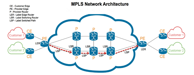
When a data packet enters an MPLS network, the entry node is called a Label Edge Router or ingress node. The class of service is then added, specifying the type of information in the packet and its priority level. In MPLS, there are predetermined, unidirectional pathways linking routers across the network; the Label Switched Path (LSP). Networks can only forward data packets after the LSP has been established and the ingress node has encapsulated the packet in the LSP.
Other nodes within the network are called the label switch routers, which are transit nodes ensuring continuous data flow. The information in the packet label guides the transit nodes, and stops are minimized. After passing through the ingress nodes and transmit nodes, the last router is called an egress node, and it removes the label so the packet address can be read and delivered to the destination.
The MPLS uses a networking protocol that is somewhat a combination of Layer 2 (data link layer) and Layer 3 (IP layer) of the Open Systems Interconnection (OSI) model. This is why MPLS is generally considered a layer 2.5 networking protocol, having features from both for data transfer across a network. Its functionality is enabled by the following
Components of the MPLS label:
- Label/label value: It is a 20-bit long field containing the information routers read in directing the data packet.
- Traffic class field: This is a 3-bit long part of the label used to set the Quality of Service and explicit congestion notification.
- Bottom of the stack: Labels can be stacked on top of each other, and the topmost label is in charge of delivery and is replaced by other labels underneath it until the transfer is complete. The last label in an MPLS header is referred to as the bottom of the stack.
- Time to Live (TTL): It is an 8-bit long label that decreases in value each time the packet hops and therefore limits the packet’s lifespan.
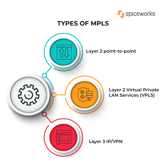
Types of MPLS
MPLS technology can be of three types. These are:
Types of MPLS
1. Layer 2 point-to-point
Layer 2 point-to-point is a type of MPLS suitable for companies that need high bandwidth connections connecting a few locations together while maintaining cost-effectiveness. Examples of practical use of layer 2 point-to-point include several network operations with their primary network infrastructure built using Ethernet and layer 2.
Layer 2 point-to-point is an excellent alternative to high bandwidth leased lines. It is not bound by internet protocol and can send data running in the Local Area Network (LAN) directly to the WAN without needing routers to change the packets to be compatible with layer 3 of the OSI model. Here are its pros and cons:
- Pros: With this type of MPLS, the need to manage complex routing tables has been eliminated. Also, it is cost-effective, as WAN connections can be directly linked with layer 2 switches, eliminating the need for expensive routers.
- Cons: It is challenging to get circuits of less than 10Mbps in bandwidth as providers only sell high bandwidth circuits. Further, it does not support point-to-multipoint connections.
2. Layer 2 Virtual Private LAN Services (VPLS)
Layer 2 Virtual Private LAN Services (also known as Layer 2 VPLS) is now becoming more sought after for its ability to provide Ethernet services. Layer 2 VPLS combines the Multi-Protocol Label Switching with the Ethernet and extends the benefits to end customers and carriers.
For over 20 years, LAN has predominantly used Ethernet switching for connectivity, while the carrier network relies on internet protocol routing. Internet protocol not only provides internet access but also provides virtual private network (VPN) access.
Ethernet, however, has continued to be widely used over various bandwidths because it requires little technical knowledge and remains more affordable. Ethernet is now the infrastructure of choice in both LAN and WAN. Virtual Private LAN Services (VPLS) is an ideal protocol that can provide its users with Multi-Protocol Label Switching and Ethernet, therefore diverting all the traffic in Layer 2 directly to the wide area network. In addition, VPLS remains simple, easy, affordable, and highly scalable. Here are its pros and cons:
- Pros: It provides a transparent interface that does not require investment in hardware such as routers to upgrade bandwidth. Traffic is labeled with a MAC address as opposed to an IP address, and like all switched networks, Layer 2 VPLS offers lower latency periods than a router network will offer. Configuration and deployment are straightforward, even for newly added sites.
- Cons: Layer 2 VPLS is still being used only in some parts of the world and has not attained global reach. Therefore this limits the applicability of any feature. The absence of routers as part of the hardware infrastructure places the layer 2 VPLS at higher risk of storm damage. Monitoring is complex due to a lack of visibility from the providers.
3. Layer 3 IP/VPN
Layer 3 IP/VPN is a type of MPLS network most suitable for large enterprises covering multiple branches over a vast land mass. This includes corporations with offices spread across the globe, industries located in more than one country, etc.
Layer 3 IP/VPN is a service that is naturally a continuation of the ATM and legacy frame relay models. Layer 3 IP/VPN transports data packets based on labels attached as the packets enter the ingress nodes. Therefore, it is highly suitable for companies that are merging for easy scalability and rapid deployment.
It is also a good fit for companies migrating from the ATM to IP or from the inflexible frame relay to IP, and also for those preparing for voice and data convergence. Layer 3 IP/VPN makes it possible for all the sites in the network to have a blanket class of service prioritization based on the type of traffic (e.g., VoIP). Here are its pros and cons:
- Pros: Layer 3 IP/VPN is highly scalable and helpful when considering fast deployment. It supportsquality of service (QOS) for differentiation of traffic types. Unlike an ATM, it does not need permanent virtual circuits yet provides the same services.
- Cons: Changing the network settings like QOS takes time and involves sending requests. Layer 3 IP/VPN is not suitable for small businesses. It offers only IP services, and must convert data from layer 2 to layer 3 before you can use it on the network.
Architecture of MPLS
MPLS architecture comprises a combination of 2 OSI layers – i.e., the second and third layers. This means that in an MPLS network, there are unique steps that a data packet must follow to get it across the MPLS domain. These steps include:
- Label creation and distribution must be done based on the FEC and dispersed among the routers with LDP protocol.
- Creation of tables at each router using the Label Forwarding Information Base (LFIB). The LFIB can be regarded as analogous to the routing table employed in the IP network.
- Label switched path creation.
- Label insertion/table lookup of data packets entering the ingress router.
Packet forwarding occurs at every router by swapping the labels until the bottom stack label is reached at the egress router. The primary architectural point of Multi-Protocol Label Switching is that one can add labels carrying additional information to data packets for transfer above what the routers previously had to use.
Apart from this, you must understand the five elements of MPLS to grasp the architecture of the network.
1. Ingress Label Edge Router (LER)
The ingress label edge router is located on the periphery and indicates a point of entry for the data packet from its source. Ingress label router imposes a label and forwards the packets to a destination. Therefore, the ingress edge router is responsible for initiating the packet forwarding operation and does this just after setting up the label switched path (LSP) and assigning proper labels.
2. Forward Equivalence Class (FEC)
The Forward Equivalence Class is a group of data packets related to one application that is forwarded in its switch path, applying the same treatment and across the same route. Therefore, all the packets of that class bear the same service requirement. Each type of data traffic is given a new forward equivalence class, which is done immediately when the packet enters the MPLS cloud.
3. Label Switch Router (LSR)
The Label Switch Router is a part of the MPLS that exchanges inbound packets with outbound ones. It also performs functions such as label removal or disposition, label addition or imposition, and label swapping. In label swapping, the label switch router replaces the topmost label in a stack with the value of an outgoing label. This router also separates data streams from the access network into the core of the MPLS, into different FECs.
4. Label Switch Path (LSP)
The Label Switch Path (LSP) is a direct pathway in the Multi-Protocol Label Switching (MPLS) enabled network that is used by a packet moving from its source to the destination. LSP is a unidirectional path that allows packets to move in only one direction. The packet passes through several intermediate routers between the origin and destination.
A labeled switched path is necessary for every MPLS network for data transfer to occur. A typical scenario involves a data packet coming in from the ingress node (LER) and migrating through different nodes through the shortest possible path, using an established LSP before getting to the egress node.
5. Egress Label Edge Router (LER)
Like the ingress LER, the Egress Label Edge Router (LER) is a router located on the MPLS network’s periphery. It serves as a point of exit for data packets that have arrived at their destination. Therefore, it removes labels (label disposition) and forwards the IP packet to the final destination. The egress LER uses a bottom-of-stack indicator to guide its function. This means it will only dispose of a label if the label on top of the stack is identified as a bottom label.
Multi-Protocol Label Switching is also separated into the control and forwarding planes:
- MPLS control plane: The responsibility of the control play is to create the label switched path. The LSP is then used for sharing the routing information through the routers and also integrates the data, creating the LFIB.
- MPLS forwarding plane: The forwarding plane directs packets throughrouters based on their labels. It uses the information in the LFIB.
Takeaway
While MPLS remains foundational to network infrastructure, its usage is waning. According to a 2021 study by Telegeography, implementation of MPLS decreased by 24% between 2019 and 2020. During this time, the adoption of SD-WAN increased, speaking to the growing preference for more agile and flexible software-based technologies.
On the other hand, MPLS involves expensive but highly reliable infrastructure which promises excellent performance, especially for real-time data transfers. As a result, certain enterprises may want to hold onto their MPLS investments and have them co-exist with new technologies.
Posted by Ajmal Ward & filed under CompTIA Network+, MICROSOFT MTA NETWORKING.
Load Balancing
Load Balancing Definition: Load balancing is the process of distributing network traffic across multiple servers. This ensures no single server bears too much demand. By spreading the work evenly, load balancing improves application responsiveness. It also increases availability of applications and websites for users. Modern applications cannot run without load balancers. Over time, load balancers have added additional capabilities including security and application acceleration
About Load Balancers
As an organization meets demand for its applications, the load balancer decides which servers can handle that traffic. This maintains a good user experience.
Load balancers manage the flow of information between the server and an endpoint device (PC, laptop, tablet or smartphone). The server could be on-premises, in a data center or the public cloud. The server can also be physical or virtualized. The load balancer helps servers move data efficiently, optimizes the use of application delivery resources and prevents server overloads. Load balancers conduct continuous health checks on servers to ensure they can handle requests. If necessary, the load balancer removes unhealthy servers from the pool until they are restored. Some load balancers even trigger the creation of new virtualized application servers to cope with increased demand.
Traditionally, load balancers consist of a hardware appliance. Yet they are increasingly becoming software-defined. This is why load balancers are an essential part of an organization’s digital strategy.
Download this report to learn how the NSX Advanced Load Balancer (Avi Networks) distributed over 1 million SSL transactions per second with the help of Intel’s high-performance CPUs
History of Load Balancing
Load balancing got its start in the 1990s as hardware appliances distributing traffic across a network. Organizations wanted to improve accessibility of applications running on servers. Eventually, load balancing took on more responsibilities with the advent of Application Delivery Controllers (ADCs). They provide security along with seamless access to applications at peak times.
ADCs fall into three categories: hardware appliances, virtual appliances (essentially the software extracted from legacy hardware) and software-native load balancers. As computing moves to the cloud, software ADCs perform similar tasks to hardware. They also come with added functionality and flexibility. They let an organization quickly and securely scale up its application services based on demand in the cloud. Modern ADCs allow organizations to consolidate network-based services. Those services include SSL/TLS offload, caching, compression, intrusion detection and web application firewalls (WAF). This creates even shorter delivery times and greater scalability.
Load Balancing and SSL
Secure Sockets Layer (SSL) is the standard security technology for establishing an encrypted link between a web server and a browser. SSL traffic is often decrypted at the load balancer. When a load balancer decrypts traffic before passing the request on, it is called SSL termination. The load balancer saves the web servers from having to expend the extra CPU cycles required for decryption. This improves application performance.
However, SSL termination comes with a security concern. The traffic between the load balancers and the web servers is no longer encrypted. This can expose the application to possible attack. However, the risk is lessened when the load balancer is within the same data center as the web servers.
Another solution is the SSL pass-through. The load balancer merely passes an encrypted request to the web server. Then the web server does the decryption. This uses more CPU power on the web server. But organizations that require extra security may find the extra overhead worthwhile.
Load Balancing and Security
Load Balancing plays an important security role as computing moves evermore to the cloud. The off-loading function of a load balancer defends an organization against distributed denial-of-service (DDoS) attacks. It does this by shifting attack traffic from the corporate server to a public cloud provider. DDoS attacks represent a large portion of cybercrime as their number and size continues to rise. Hardware defense, such as a perimeter firewall, can be costly and require significant maintenance. Software load balancers with cloud offload provide efficient and cost-effective protection.

Load Balancing Algorithms
There is a variety of load balancing methods, which use different algorithms best suited for a particular situation.
- Least Connection Method — directs traffic to the server with the fewest active connections. Most useful when there are a large number of persistent connections in the traffic unevenly distributed between the servers.
- Least Response Time Method — directs traffic to the server with the fewest active connections and the lowest average response time.
- Round Robin Method — rotates servers by directing traffic to the first available server and then moves that server to the bottom of the queue. Most useful when servers are of equal specification and there are not many persistent connections.
- IP Hash — the IP address of the client determines which server receives the request.
Load balancing has become a necessity as applications become more complex, user demand grows and traffic volume increases. Load balancers allow organizations to build flexible networks that can meet new challenges without compromising security, service or performance.
Load Balancing Benefits
Load balancing can do more than just act as a network traffic cop. Software load balancers provide benefits like predictive analytics that determine traffic bottlenecks before they happen. As a result, the software load balancer gives an organization actionable insight. These are key to automation and can help drive business decisions.
In the seven-layer Open System Interconnection (OSI) model, network firewalls are at levels one to three (L1-Physical Wiring, L2-Data Link and L3-Network). Meanwhile, load balancing happens between layers four to seven (L4-Transport, L5-Session, L6-Presentation and L7-Application).
Load balancers have different capabilities, which include:
- L4 — directs traffic based on data from network and transport layer protocols, such as IP address and TCP port.
- L7 — adds content switching to load balancing. This allows routing decisions based on attributes like HTTP header, uniform resource identifier, SSL session ID and HTML form data.
- GSLB — Global Server Load Balancing extends L4 and L7 capabilities to servers in different geographic locations.
More enterprises are seeking to deploy cloud-native applications in data centers and public clouds. This is leading to significant changes in the capability of load balancers. In turn, this creates both challenges and opportunities for infrastructure and operations leaders.
Posted by Ajmal Ward & filed under CompTIA Network+, MICROSOFT MTA NETWORKING.
IMAP Protocol
IMAP stands for Internet Message Access Protocol. It is an application layer protocol which is used to receive the emails from the mail server. It is the most commonly used protocols like POP3 for retrieving the emails.
It also follows the client/server model. On one side, we have an IMAP client, which is a process running on a computer. On the other side, we have an IMAP server, which is also a process running on another computer. Both computers are connected through a network.

The IMAP protocol resides on the TCP/IP transport layer which means that it implicitly uses the reliability of the protocol. Once the TCP connection is established between the IMAP client and IMAP server, the IMAP server listens to the port 143 by default, but this port number can also be changed.
By default, there are two ports used by IMAP:
- Port 143: It is a non-encrypted IMAP port.
- Port 993: This port is used when IMAP client wants to connect through IMAP securely.
Why should we use IMAP instead of POP3 protocol?
POP3 is becoming the most popular protocol for accessing the TCP/IP mailboxes. It implements the offline mail access model, which means that the mails are retrieved from the mail server on the local machine, and then deleted from the mail server. Nowadays, millions of users use the POP3 protocol to access the incoming mails. Due to the offline mail access model, it cannot be used as much. The online model we would prefer in the ideal world. In the online model, we need to be connected to the internet always. The biggest problem with the offline access using POP3 is that the mails are permanently removed from the server, so multiple computers cannot access the mails. The solution to this problem is to store the mails at the remote server rather than on the local server. The POP3 also faces another issue, i.e., data security and safety. The solution to this problem is to use the disconnected access model, which provides the benefits of both online and offline access. In the disconnected access model, the user can retrieve the mail for local use as in the POP3 protocol, and the user does not need to be connected to the internet continuously. However, the changes made to the mailboxes are synchronized between the client and the server. The mail remains on the server so different applications in the future can access it. When developers recognized these benefits, they made some attempts to implement the disconnected access model. This is implemented by using the POP3 commands that provide the option to leave the mails on the server. This works, but only to a limited extent, for example, keeping track of which messages are new or old become an issue when both are retrieved and left on the server. So, the POP3 lacks some features which are required for the proper disconnected access model.
In the mid-1980s, the development began at Stanford University on a new protocol that would provide a more capable way of accessing the user mailboxes. The result was the development of the interactive mail access protocol, which was later renamed as Internet Message Access Protocol.
IMAP History and Standards
The first version of IMAP was formally documented as an internet standard was IMAP version 2, and in RFC 1064, and was published in July 1988. It was updated in RFC 1176, August 1990, retaining the same version. So they created a new document of version 3 known as IMAP3. In RFC 1203, which was published in February 1991. However, IMAP3 was never accepted by the market place, so people kept using IMAP2. The extension to the protocol was later created called IMAPbis, which added support for Multipurpose Internet Mail Extensions (MIME) to IMAP.
This was a very important development due to the usefulness of MIME. Despite this, IMAP is was never published as an RFC. This may be due to the problems associated with the IMAP3. In December 1994, IMAP version 4, i.e., IMAP4 was published in two RFCs, i.e., RFC 1730 describing the main protocol and RFC 1731 describing the authentication mechanism for IMAP 4. IMAP 4 is the current version of IMAP, which is widely used today. It continues to be refined, and its latest version is actually known as IMAP4rev1 and is defined in RFC 2060. It is most recently updated in RFC 3501.
IMAP Features
IMAP was designed for a specific purpose that provides a more flexible way of how the user accesses the mailbox. It can operate in any of the three modes, i.e., online, offline, and disconnected mode. Out of these, offline and disconnected modes are of interest to most users of the protocol.
The following are the features of an IMAP protocol:
- Access and retrieve mail from remote server: The user can access the mail from the remote server while retaining the mails in the remote server.
- Set message flags: The message flag is set so that the user can keep track of which message he has already seen.
- Manage multiple mailboxes: The user can manage multiple mailboxes and transfer messages from one mailbox to another. The user can organize them into various categories for those who are working on various projects.
- Determine information prior to downloading: It decides whether to retrieve or not before downloading the mail from the mail server.
- Downloads a portion of a message: It allows you to download the portion of a message, such as one body part from the mime-multi part. This can be useful when there are large multimedia files in a short-text element of a message.
- Organize mails on the server: In case of POP3, the user is not allowed to manage the mails on the server. On the other hand, the users can organize the mails on the server according to their requirements like they can create, delete or rename the mailbox on the server.
- Search: Users can search for the contents of the emails.
- Check email-header: Users can also check the email-header prior to downloading.
- Create hierarchy: Users can also create the folders to organize the mails in a hierarchy.
IMAP General Operation
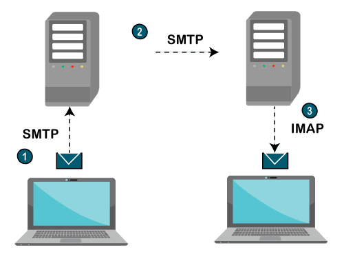
- The IMAP is a client-server protocol like POP3 and most other TCP/IP application protocols. The IMAP4 protocol functions only when the IMAP4 must reside on the server where the user mailboxes are located. In c the POP3 does not necessarily require the same physical server that provides the SMTP services. Therefore, in the case of the IMAP protocol, the mailbox must be accessible to both SMTP for incoming mails and IMAP for retrieval and modifications.
- The IMAP uses the Transmission Control Protocol (TCP) for communication to ensure the delivery of data and also received in the order.
- The IMAP4 listens on a well-known port, i.e., port number 143, for an incoming connection request from the IMAP4 client.
Let's understand the IMAP protocol through a simple example.
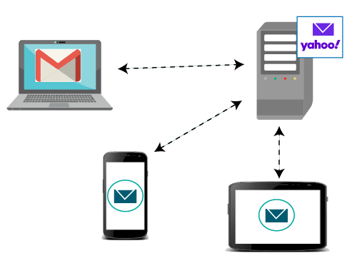
The IMAP protocol synchronizes all the devices with the main server. Let’s suppose we have three devices desktop, mobile, and laptop as shown in the above figure. If all these devices are accessing the same mailbox, then it will be synchronized with all the devices. Here, synchronization means that when mail is opened by one device, then it will be marked as opened in all the other devices, if we delete the mail, then the mail will also be deleted from all the other devices. So, we have synchronization between all the devices. In IMAP, we can see all the folders like spam, inbox, sent, etc. We can also create our own folder known as a custom folder that will be visible in all the other devices.
Posted by Ajmal Ward & filed under CompTIA Network+, MICROSOFT MTA NETWORKING.
HTTP
The Hypertext Transfer Protocol (HTTP) is an application-level protocol for distributed, collaborative, hypermedia information systems. This is the foundation for data communication for the World Wide Web (i.e. internet) since 1990. HTTP is a generic and stateless protocol which can be used for other purposes as well using extensions of its request methods, error codes, and headers.
Basically, HTTP is a TCP/IP based communication protocol, that is used to deliver data (HTML files, image files, query results, etc.) on the World Wide Web. The default port is TCP 80, but other ports can be used as well. It provides a standardized way for computers to communicate with each other. HTTP specification specifies how clients’ request data will be constructed and sent to the server, and how the servers respond to these requests.
Basic Features
There are three basic features that make HTTP a simple but powerful protocol:
- HTTP is connectionless:The HTTP client, i.e., a browser initiates an HTTP request and after a request is made, the client waits for the response. The server processes the request and sends a response back after which client disconnect the connection. So client and server knows about each other during current request and response only. Further requests are made on new connection like client and server are new to each other.
- HTTP is media independent:It means, any type of data can be sent by HTTP as long as both the client and the server know how to handle the data content. It is required for the client as well as the server to specify the content type using appropriate MIME-type.
- HTTP is stateless:As mentioned above, HTTP is connectionless and it is a direct result of HTTP being a stateless protocol. The server and client are aware of each other only during a current request. Afterwards, both of them forget about each other. Due to this nature of the protocol, neither the client nor the browser can retain information between different requests across the web pages.
HTTP/1.0 uses a new connection for each request/response exchange, where as HTTP/1.1 connection may be used for one or more request/response exchanges.
Basic Architecture
The following diagram shows a very basic architecture of a web application and depicts where HTTP sits:
The HTTP protocol is a request/response protocol based on the client/server based architecture where web browsers, robots and search engines, etc. act like HTTP clients, and the Web server acts as a server.
Client
The HTTP client sends a request to the server in the form of a request method, URI, and protocol version, followed by a MIME-like message containing request modifiers, client information, and possible body content over a TCP/IP connection.
Server
The HTTP server responds with a status line, including the message’s protocol version and a success or error code, followed by a MIME-like message containing server information, entity meta information, and possible entity-body content.
Posted by Ajmal Ward & filed under CompTIA Network+, MICROSOFT MTA NETWORKING.
File Transfer Protocol (FTP)
The full form of FTP is File Transfer Protocol. It is a standard internet protocol provided by TCP/IP which is used for transmitting the files from one system to another system.
The main purpose of FTP is for transferring the web page files from one system to the computer which acts as a server for other computers on the internet. It is also helpful for downloading the files to compute from other servers.
Objectives
The objectives of FTP are as follows −
- FTP provides file sharing.
- FTP helps us to encourage the use of remote computers.
- FTP used to transfer the data reliably and efficiently.
Features
The features of FTP are as follows −
- Data representation
- File organization and Data structures
- Transmission modes
- Error control
- Access control
TCP Connections
For file transferring, two TCP connections are used which are as follows −
- Control connection− For sending control information like user identification, password, commands to change the remote directory, commands to retrieve and store files, etc. FTP makes use of control connections. It is initiated with port number 21.
- Data Connection− For sending the actual file, FTP makes use of data connection. It is initiated with port number 20.
Given below is the diagram of the TCP Connections −

FTP session
When an FTP session is started between a client and servers, the client initiates a control TCP connection with the server side. The client sends control information over this. When the server receives this, it initiates a data connection to the client side. At a time only one file can be sent over one data connection. FTP has to maintain information about its user throughout the session.
Data Structures
FTP allows three types of data structures, which are as follows −
- File structure− It is a continuous sequence of data bytes.
- Record structure− In this, the file is made up of sequential records.
- page structure− In this, the file is made up of independent indexed pages.
FTP Servers
FTP servers are divided into two parts for separating the general public users from more private users −
- Anonymous Server− FTP sites allow anonymous FTP do not require a password for access. We have to log in as anonymous and enter our email address as password.
- Non-anonymous server− If we are using a non-anonymous server, then we will log in as you and give our password.
FTP commands
The FTP commands are as follows −
- USER – Sending user identification to the server.
- PASS – sending user password to the server.
- PWD – It causes the name of the current working directory to be returned in the reply.
Working Procedure
Clients initiate a conversation with servers by requesting to download a file. With the help of FTP, a client can delete, upload, download, rename etc. and even copy files on a server. A user typically needs to log on to the FTP server to use the available content.
Advantages
The advantages of FTP are as follows −
- Speed
- Efficient
- Security
- Back & Forth movement
Disadvantages
The disadvantages of FTP are as follows −
- FTP is not compatible with every system.
- Attackers can quickly identify the FTP password.
- Does not allow running of simultaneous transfers to multiple receivers.
Posted by Ajmal Ward & filed under CompTIA Network+, MICROSOFT MTA NETWORKING.
Difference between Private and Public IP addresses
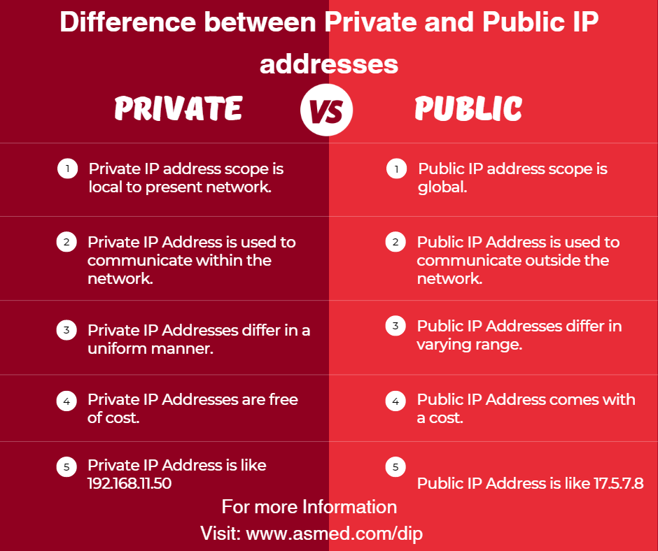
What is an IP Address?
An IP address (Internet Protocol address) is a numerical identifier, such as 192.0.2.1, that is associated with a computer network that communicates using the Internet Protocol. An IP address is used for two purposes: identifying a host or network interface, and addressing a specific location.
An IP address has two primary functions: it identifies the host, or more particularly its network interface; and it indicates the host’s position in the network, allowing a path to be established to that host.
IP addresses can be either Public or Private. Read through this article to find out how a Public IP address is different from a Private IP address.
What is a Public IP Address?
Your internet service provider assigns a public IP address to your network router so that it may be accessed directly over the internet (ISP). When you connect to the internet using your router’s public IP, your personal device has a private IP address that is concealed.
Connecting to the internet using a public IP address is similar to sending mail to a P.O. box rather than giving out your home address. It’s a little safer, but it’s a lot more noticeable.
What is a Private IP Address?
The address that your network router provides to your device is known as a private IP address. Each device on the same internal network is given a unique private IP address (also known as a private network address) that allows them to communicate with one another.
Private IP addresses enable devices on the same network to interact without needing to connect to the internet. Private IPs assist to strengthen security within a specified network, such as your home or workplace, by making it more difficult for an external host or user to establish a connection. This is why you can print papers from your home printer using a wireless connection, but your neighbor can’t send their files to your printer accidentally.
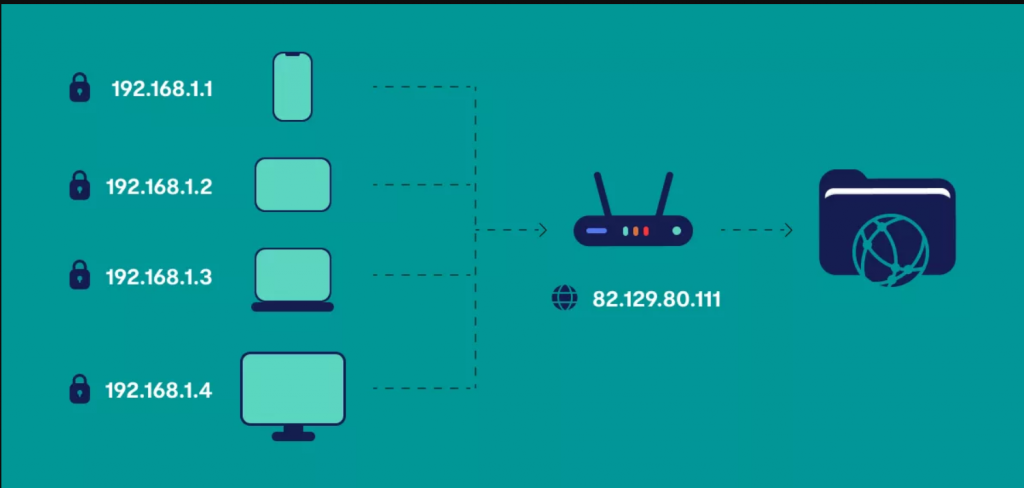
Difference between Private and Public IP Addresses
The following table highlights the major differences between Private and Public IP addresses −
Key | Private IP Address | Public IP Address |
Scope | Private IP address scope is local to present network. | Public IP address scope is global. |
Communication | Private IP Address is used to communicate within the network. | Public IP Address is used to communicate outside the network. |
Format | Private IP Addresses differ in a uniform manner. | Public IP Addresses differ in varying range. |
Provider | Local Network Operator creates private IP addresses using network operating system. | Internet Service Provider (ISP) controls the public IP address. |
Cost | Private IP Addresses are free of cost. | Public IP Address comes with a cost. |
Locate | Private IP Address can be located using ipconfig command. | Public IP Address needs to be searched on search engine like google. |
Range | Private IP Address range: 10.0.0.0 – 10.255.255.255, 172.16.0.0 – 172.31.255.255, 192.168.0.0 – 192.168.255.255 | Except private IP Addresses, rest IP addresses are public. |
Example | Private IP Address is like 192.168.11.50. | Public IP Address is like 17.5.7.8. |
Conclusion
Private IP Address and Public IP Address are used to uniquely identify a machine on the Internet. Private IP address is used with a local network and public IP address is used outside the network. Public IP address is provided by the Internet Service Provider (ISP).
A public IP address is a one-of-a-kind numeric code that is never repeated by other devices, whereas a private IP address is a non-unique numeric code that can be reused by other private network devices.
Posted by Ajmal Ward & filed under CompTIA Network+, MICROSOFT MTA NETWORKING.
How to prepare for CompTIA Network + Job?
Posted by Ajmal Ward & filed under CompTIA Network+, MICROSOFT MTA NETWORKING.
Server Message Block Protocol (SMB)
The Server Message Block (SMB) Protocol is a Microsoft Windows protocol that allows users to share files, printers, and serial ports across a network. SMBv2 is the most recent version released with Windows Vista and has undergone more revisions under Windows 7.
The IBM-developed Server Message Block protocol is a networking protocol. In the 1990s, Microsoft upgraded the protocol, allowing Windows-based networks to create, alter, and delete shared files, printers, and serial ports.
SMB is an application layer protocol that interacts through TCP port 445 in most deployments. Compared to similar protocols such as the File Transfer Protocol (FTP), SMB quickly gained popularity since it offers far more flexibility.
An application known as Samba allows Linux systems to interact with the SMB protocol in Linux settings. The open-source variant of SMB is the Common Internet File System (CIFS).
How Does SMB Work?
The Server Message Block protocol allows clients to communicate with other network users and access their files and services. The other system must have also implemented the network protocol and used an SMB server to receive and execute client requests. Both parties, however, must first create a link, sending equivalent messages to each other.
SMB uses the Transmission Control Protocol (TCP) in IP networks, requiring a three-way handshake before communicating between the client and the server. The TCP protocol governs subsequent data transmission.
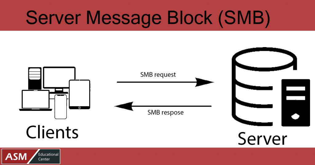
Versions of SMB Protocol
Following is the list of SMB Protocol Versions −
- IBM released SMBv1 in 1984 as a DOS file-sharing protocol. In 1990, Microsoft revised and enhanced it.
- In 1996, a new version of CIFS was launched, with more excellent capabilities and support for higher file sizes. It was bundled with the latest Windows 95 operating system.
- In 2006, Windows Vista introduced SMBv2. It had a noticeable performance boost, thanks to enhanced efficiency; fewer instructions and subcommands meant faster execution.
- Windows 7 had SMBv2.1, which was an enhanced performance.
- With Windows 8, SMBv3 was introduced, along with many improvements. The protocol now supports end-to-end encryption, which is the most noticeable improvement.
- 02 was released alongside Windows 8.1. By eliminating SMBv1, it provided the possibility to improve security and speed.
- With Windows 10, SMBv3.1.1 was launched in 2015. It improved the protocol’s security by including AES-128 encryption, protection against man-in-the-middle attacks, and session verification.
Knowing which version of the SMB protocol your device uses is critical if you own a business and have several Windows devices connected. It would be difficult to find a PC running Windows 95 or XP (and using SMBv1) in a modern office, but they may still be running on outdated servers.
Is SMB Safe to Use?
While different versions of SMB give varying levels of security and protection, hackers have uncovered a vulnerability in SMBv1 that they can use to execute their malware without the user’s knowledge. When a device becomes infected, it infects all other connected devices. The National Security Agency (NSA) detected the bug in 2017.
The exploit was called Eternal Blue, and it was stolen from the NSA and distributed online by the Shadow Brokers hacker group. Microsoft patched the vulnerability, but the WannaCry ransomware attack hit the world barely a month later.
Security Precautions
Given the WannaCry and Not Petya ransomware, as well as multiple other vulnerabilities revealed in the most recent SMB version (v3.1.1), such as SMB Ghost and SMBleed, many network administrators and security professionals are questioning whether it should be utilized on networks. SMB, in general, is regarded as a secure protocol when it is updated and patched.
However, the following steps should be taken to mitigate any security vulnerabilities posed by SMB −
- SMBv1 should not be used since it lacks encryption, is inefficient, and new significant issues comparable to the MS17-010 vulnerabilities could appear in the future due to its complex implementation.
- When possible, use the most recent SMB version (SMBv3.1.1 as of the date of this post). SMBv3.1.1 is more efficient than previous SMB versions and has cutting-edge security measures.
- SMB access should be limited to trustworthy networks and clients as a best security practice (Least Privilege).
- Finally, if SMB functionality is not required, it should be deactivated on Windows systems to decrease the overall attack surface and disclose as little fingerprinting information to attackers as feasible.
Posted by Ajmal Ward & filed under CompTIA Network+, MICROSOFT MTA NETWORKING.
What is VPN in Computer Network?
VPN stands for Virtual Private Network. It allows you to connect your computer to a private network, creating an encrypted connection that masks your IP address to securely share data and surf the web, protecting your identity online.
A virtual private network, or VPN, is an encrypted connection over the Internet from a device to a network. The encrypted connection helps ensure that sensitive data is safely transmitted. It prevents unauthorized people from eavesdropping on the traffic and allows the user to conduct work remotely. VPN technology is widely used in corporate environments.
A VPN connection is shown in the figure below −
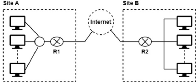
In this figure, Routers R1 and R2 use VPN technology to guarantee privacy for the organization.
VPN connections are used in two important ways −
- To establish WAN connections using VPN technology between two distant networks that may be thousands of miles apart, but where each has some way of accessing the internet.
- To establish remote access connections that enable remote users to access a private network through a public network like the internet.
Types of VPNs
Router VPN
The first type uses a router with added VPN capabilities. A VPN router cannot only handle normal routine duties, but it can also be configured to form VPNs over the internet to other similar routers located in remote networks.
Firewall VPN
The second type of VPN is one built into a firewall device. Firewall VPN can be used both to support remote users and also to provide VPN links.
Network Operating System
The third type of VPNs include those offered as part of a network operating system like Windows NT, Windows 2000, and Netware 5. These VPNs are commonly used to support remote access, and they are generally the least expensive to purchase and install.
Posted by Ajmal Ward & filed under CompTIA Network+, MICROSOFT MTA NETWORKING.
Single Mode vs. Multimode Fiber Optic Cables

Many decisions come into play when installing fiber optic cabling. By far, one of the most important questions is whether to install single mode or multimode. This decision has huge implications for your network’s distance, bandwidth, and budget, so it’s vital to understand the differences between these two types of fiber optic glass.
Before we discuss each type of fiber, here are some definitions:
Optical fiber: The glass portion of a fiber optic cable – no jacketing or strength members included. An optical fiber is made up of a light carrying core surrounded by cladding. The cladding prevents light from escaping the core, effectively keeping the signal moving down the glass.
Single mode fiber: a fiber featuring a small light-carrying core of about 9 micrometers (µm) in diameter. For reference, a human hair is closer to 100 µm. The core is surrounded by a cladding that brings the overall diameter of the optical fiber to 125 µm.
Multimode fiber: a fiber with a core of 50 µm or above. A larger core means multiple modes (or rays of light) can travel down the core simultaneously. Just like single mode, the core is surrounded by a cladding that brings the overall diameter of the optical fiber to 125 µm.

Common Misconceptions
It’s important to remember that (without the visual acuity of Superman) there is no way to distinguish between single mode and multimode optical fibers with the naked eye. As noted above, standard optical fibers have cladding around the core that brings the diameter of the optical fiber itself to 125 µm. When you put a connector on an optical fiber, you are primarily seeing the cladding and any integral protective coating, like SSF™ polymer.
The terms “single mode” and “multimode” also have no relation to the number of optical fibers in the fiber optic cable you are running. It’s possible to have a cable containing 144 single mode optical fibers, and it’s also possible to have a cable containing 144 multimode optical fibers.
Is Multimode Better?
To installers new to fiber, multimode fiber may seem appealing because the name implies that more can be sent over the cable. However, “multimode” refers to multiple rays of light simultaneously taking different tracks down the core of the fiber. This characteristic, enabled by multimode’s larger core, actually creates some limitations.

In multimode fiber, light travels down the core, bouncing off the cladding as it goes. As each beam of light has an individual path, each will reach the end of the optical fiber at different times. This spread is modal dispersion, and it creates limits on data and distance. For OM3 multimode, 10 Gbs can be sent a maximum of about 300 meters or 1000 feet before the signal becomes indistinguishable.
For OM3 multimode, 10 Gbs can be sent a maximum of about 300 m (1000 ft) before the signal becomes indistinguishable.

Conversely, single mode’s minuscule core limits dispersion, so higher bandwidth signals can be sent over a longer distance. Sending data over the ocean floor? Single mode would be the cable for you. In general, single mode is the cable of choice for installations above about 300 m (1000 ft).
Single Mode Distance Limitations1
TYPE | APPLICATION | DISTANCE | WAVELENGTH |
Gigabit | 1000BASE-LX | 5 km | 1310 nm |
10 Gigabit | 10GBASE-LX4 | 10 km | 1310 nm |
10 Gigabit | 10GBASE-E | 40 km | 1550 nm |
40 Gigabit | 40GBASE-LR4 | 10 km | 1310 nm |
40 Gigabit | 40GBASE-FR | 2 km | 1310 nm |
100,Gigabit | 100GBASE-LR4 | 10 km | 1310 nm |
Why Run Multimode at All?
The answer to this comes down primarily to budget and applications. Single mode cable requires single mode transceivers, and those tend to be far more expensive than multimode equivalents. The difference in electronics can bring single mode system costs far above those of multimode, even if the per foot cost of single mode cable is low. This is one of the primary reasons we’ll generally recommend multimode before single mode fiber in lower-distance applications.
However, there are still times when single mode may be recommended for short cable runs. It depends on the installation!
Choosing Multimode? Pick the Right Grade.
Multimode fiber is currently constructed in five different grades: OM1, OM2, OM3, OM4, and OM5. Each grade of multimode fiber has a different bandwidth and distance limitation, with OM4 and OM5 providing the greatest bandwidth over longest distance and OM1 providing the lowest. At the moment, our general grade recommendation for installations suitable for multimode is OM3. As can be seen in the table below, OM3 provides good options for bandwidth over distance, and it is generally more cost-effective than OM4.
It is extremely important to note that while OM2, OM3, OM4, and OM5 all have a core of 50 µm, OM1 has a core of 62.5 µm. While these optical fibers are all surrounded by a cladding to 125 µm, OM1 can’t be used as a patch cable in a system involving OM2/OM3/OM4/OM5, and it will not work with connectors rated for OM2/OM3/OM4/OM5.
CABLE TYPE | 10 GB ETHERNET DISTANCE | 40 GB/100 GB ETHERNET DISTANCE |
OM1 Fiber | 33 m / 100 ft | N/A |
OM2 Fiber | 82 m / 260 ft | N/A |
OM3 Fiber | 300 m / 1000 ft | 100 m / 330 ft |
OM4 Fiber | 400 m / 1300 ft | 150 m / 500 ft |
OM5 Fiber | 400 m / 1300 ft | 150 m / 500 ft |
Don’t Mix and Match
Just as it’s important to note that you can’t mix OM1 and OM4, also note that single mode and multimode are not interchangeable. Single mode electronics and connectors only work with single mode fiber, and multimode, likewise, only works with multimode. This is due to the difference in core diameters between fiber types, as well as light wavelengths used for transmission.
Both single mode and multimode fibers provide excellent solutions for durable, high bandwidth installations. Being aware of the differences between the two types of fiber will allow you to select the fiber most appropriate for your installation and data requirements.
The Short Version
- Single mode fiber has a smaller core than multimode and is suitable for long haul installations. Single mode systems are generally more expensive.
- Multimode fiber has a larger core and is recommended for fiber runs less than 400 m (1300 feet). The grade of multimode fiber affects its distance and bandwidth capabilities. Multimode systems are generally less expensive.
- Single mode only works with single mode, and multimode only works with multimode. This is true for cable, connectors, and electronics.
- Our recommendation for cable runs under 300 m (1000 ft) is generally multimode OM3. This provides high bandwidth and is more budget friendly than OM4.
Posted by Ajmal Ward & filed under CompTIA Network+, MICROSOFT MTA NETWORKING.
Network Time Protocol (NTP)
NTP is an internet protocol that’s used to synchronize the clocks on computer networks to within a few milliseconds of universal coordinated time (UTC). It enables devices to request and receive UTC from a server that, in turn, receives precise time from an atomic clock.
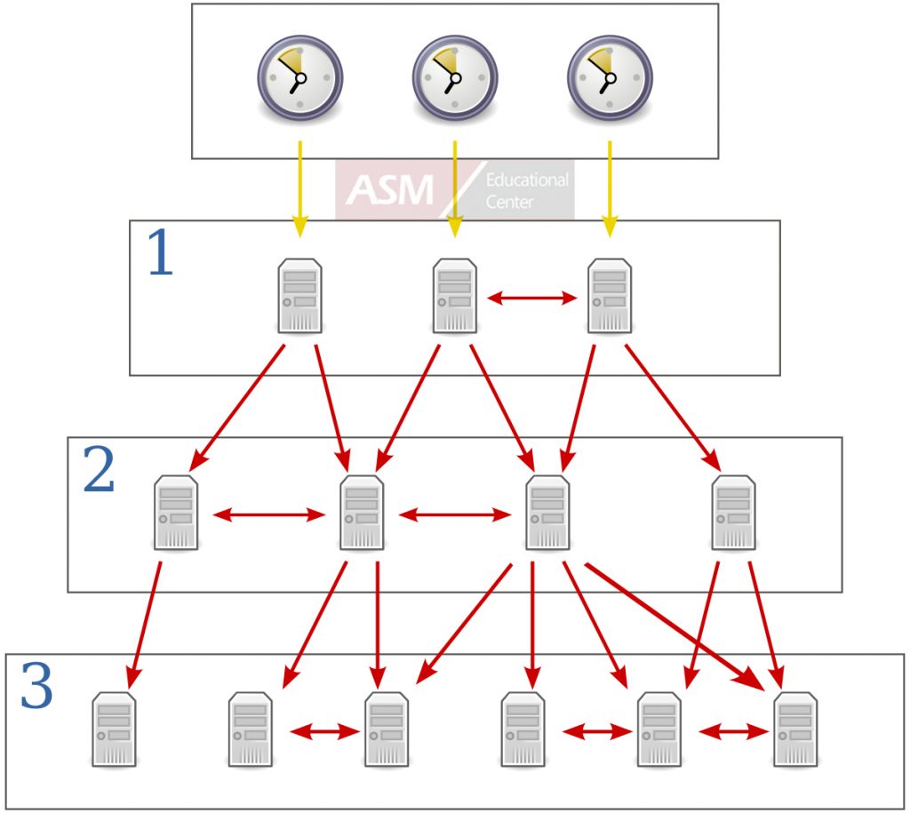
What Is NTP?
“A man with one watch knows what time it is. A man with two watches is never sure.”
Segal’s law pokes fun at the person who makes no effort to check they’re right while highlighting the complexity of receiving information from more than one source.
When it comes to synchronizing your operations, network time protocol (NTP) solves both problems, providing users with the certainty of accurate time across a whole network of devices.
Like any network protocol, NTP is a set of rules, or conventions, that dictate how devices on a network should transmit, receive and understand data. Think about it as a shared language, allowing devices to communicate, in this instance, about time.
NTP allows networked devices, such as clocks, phones and computers, to request and receive time from a server that, in turn, receives precise time from a definitive time source, like an atomic clock.
NTP was developed in the 1980s and is now on version four. Since its release, it’s been used to synchronize the critical systems of businesses, organizations and governments all over the world.
Why Is Time Synchronization Important?
Precise time is vital to everyday life.
As life becomes digitized and automated, exact time is increasingly important:
- The telecommunications industry relies on accurate time for the transfer of vast amounts of data.
- Utility companies use time synchronization to manage power distribution.
- Financial services need exact time to timestamp transactions and ensure traceable records.
- Satellite navigation depends on precise time, with a difference of one microsecond causing a positioning error of 300 metres.1
- CCTV and speed cameras require an accurate timestamp to be admissible as evidence.
- Countless businesses rely on precise time to manage their day-to-day processes, such as synchronizing clocking-in systems.
For organizations of any size, NTP is a cost-effective, reliable and user-friendly method of distributing precise time throughout a network, allowing users to boost productivity, improve customer service, enhance security and more.
Moreover, by using NTP to synchronize to UTC—a global time standard—organizations and governments are able to coordinate international operations.
What Is UTC and How Is It Decided?
UTC is the standard the world has agreed on as the basis for civil time. It’s the result of a decades-long process of invention, revision and collaboration, during which time the standard moved from Greenwich Mean Time (GMT) to Atomic Time (TAI), to UTC.
Importantly, UTC is a time standard, not a time zone, which means it’s the same all over the world and isn’t affected by daylight savings. In fact, time zones are expressed according to their offset from UTC (+/- the number hours). UTC is maintained by comparing more than 200 atomic clocks located all over the world. The Bureau International des Poids et Measures (BIPM), in France, is responsible for collating this data and generating definitive UTC time.
How Does NTP Work?
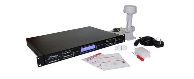
A time server and antenna can synchronize a network to UTC.
NTP makes UTC available to an organization by taking a time signal from one, or more, atomic clocks and distributing it to networked devices.
At its most basic, an NTP network is comprised of the devices to be synchronized (known as clients) and an NTP server, which receives UTC time and provides it to the clients.
The clients and server communicate in a series of requests and responses:
- The client sends an NTP request packet to the time server, stamping the time as it does so (the origin timestamp).
- The server stamps the time when the request packet is received (the receive timestamp).
- The server stamps the time again when it sends a response packet back to the client (the transmit timestamp).
- The client stamps the time when the response packet is received (the destination timestamp).
This process may only take microseconds, but the timestamps allow the client to account for the roundtrip delay and work out the difference between its internal time and that provided by the server, adjusting itself as necessary and maintaining synchronization.
NTP Hierarchy: Stratum Levels Explained
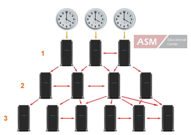
Devices on one stratum can provide time to devices on the next.
On large networks, there may be so many clients that the server can’t handle requests from all of them. In these instances, servers and clients are arranged in a hierarchy of levels called stratums.
Stratum one servers have a direct connection, via a radio or GPS signal, with the primary time source, and they provide that time to clients on stratum two via a network connection.
In turn, stratum two devices can function like a server by providing time to clients on stratum three, and those on stratum three can provide it to those on stratum four—and so on. In this way, stratum one devices aren’t overloaded with too many requests.
A total of 15 synchronized stratum levels are possible (stratum 16 is for unsynchronized clients), but each one introduces another layer of network delay, causing accuracy to decrease. To combat this, NTP clients can be set up to request time from multiple servers to help them determine the correct time as closely as possible.
What Is SNTP and How Is It Different?
Simple network time protocol (SNTP) is exactly what its name suggests: a stripped-down version of NTP that’s suited to small networks and computers with limited processing power.
SNTP and NTP share several similarities. For example, the packets of data exchanged between the clients and the time server are identical, making any time server compatible with both.
However, SNTP lacks the many algorithms that NTP uses to determine and maintain synchronization.
Practically, for instance, NTP calculates the drift rate of a given clock from the true time and adjusts that rate to maintain the clock’s synchronization. SNTP, on the other hand, allows the clock to drift and then jumps the time forward or back to match the true time at given intervals.
Between these intervals, it’s possible for the clock to be out of sync, making SNTP unsuitable for applications that demand the highest levels of precision.
SNTP also differs in the number of servers it uses for synchronization. Whereas NTP allows clients on one stratum to act as servers to clients on the next, SNTP is based on a single server-client relationship.
Additional time servers can be specified as backups, but SNTP, unlike NTP, is unable to communicate with several servers in order to discern which is the most accurate. SNTP was released in the early 1990s to suit the limited processing power of the computers of the day. Today, there are few instances where NTP can’t be handled, but SNTP can still be useful for simple applications that don’t require the higher level of precision provided by NTP.
Public NTP Servers vs. Local NTP Servers
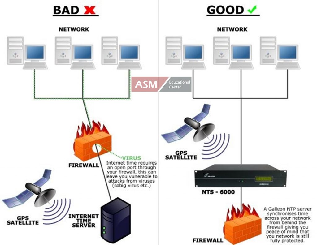
Local NTP servers sit inside your firewall, avoiding the vulnerabilities caused by public servers.
There are two types of NTP servers that you can use to provide UTC time to your network: public servers and local servers.
A public time server is owned and operated by a third party who makes it available for use over the internet. The NTP Pool Project provides an online directory of public servers, allowing you to direct your clients to one of these, free of charge.
Local (aka internal) NTP servers are those you own yourself and install in your premises, establishing a physical network connection between your servers and clients.
If synchronized time is critical to your operations, then internal time servers are the safer, more reliable option. They provide improved accuracy and more control while avoiding the various drawbacks of public servers:
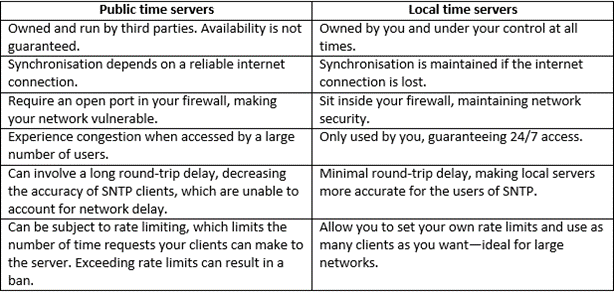
How to Synchronize Your Network with an Internal NTP Server
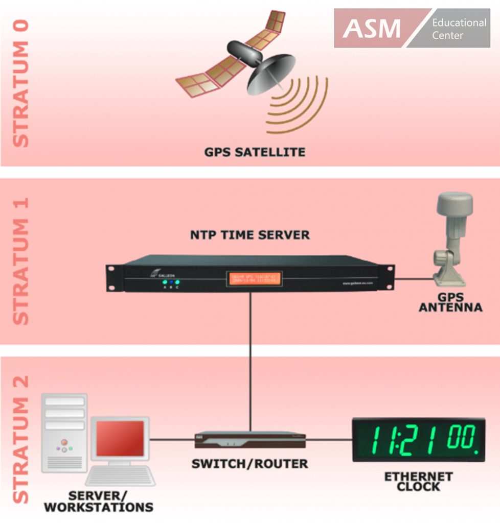
typical set up uses NTP to synchronize a network to a GPS time signal.
To set up an NTP network with an internal time server, you need a number of things:
- A reference clock/time source that defines and transmits the true time.
- A time receiver, in the form of a radio or GPS antenna.
- An NTP server, which receives the time from the antenna and delivers it to a network.
- The devices/clients to be synchronized.
Reference Clocks
A reference clock is the primary time source that defines and provides UTC time. Atomic clocks are the most accurate type of reference clock, providing near-inconceivable levels of precision.
For instance, the NIST-F2, created by the US National Institute of Standards and Technology, measures the vibration of a cesium atom to define a second (9,192,631,770 vibrations per second). If run without interruption, the clock would neither gain or lose one second in 300 million years.
Thankfully, you don’t need to install an atomic clock in your server room to receive precise time. They’re installed in the satellites of the global positioning system, and they’re maintained in the laboratories of national standards agencies all over the world. These clocks transmit time signals that you can pick up and use to synchronize your own network.
Time Receivers
GPS antennas can receive a time signal from multiple satellites.
Each GPS satellite transmits a time signal that anyone can receive with a GPS antenna. The global positioning system is designed so that at least four satellites are constantly available from anywhere in the world, making it a highly reliable source of accurate time.
Alternatively, radio antennas receive a time signal from one of several atomic clocks on earth. The range of these signals is localized, so users have to consider which station provides the strongest signal and use an antenna that’s set to that frequency.
GPS time signals are the most accurate and have the advantage of being globally available. However, the antenna requires a 360° view of the sky, which isn’t possible in every situation.
Radio time signals, on the other hand, can be received through windows, making a radio time source a good option for premises that don’t have an unobstructed view of the sky.
However, a radio time signal can be affected by topography and downtime, making it less reliable and not ideal for synchronizing very critical systems.
Either way, the receiver connects to an internal NTP server via a cable that can be up to 1,000 meters long, when used with a power booster, giving businesses lots of flexibility when it comes to installation.
Internal NTP Servers
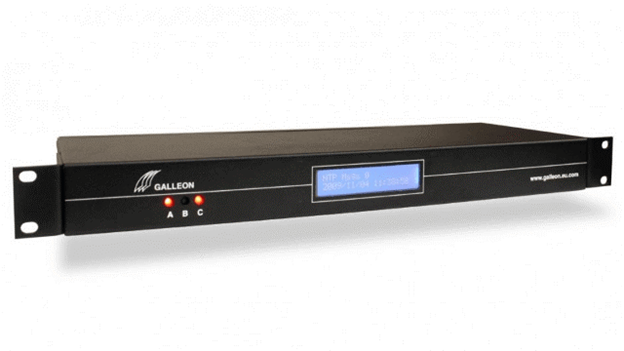
A rackmount NTP server installs easily alongside your existing IT hardware.
An NTP server receives the time from the reference clock, via the antenna, and provides it to your network.
The type of server you choose will depend on a number of factors:
- Whether you’re using a GPS or radio time source.
- How many clients you want to synchronize.
- Whether or not you want to supply time to multiple networks.
- What operating system you want to use.
- How you want to physically install the server.
Choose a radio or GPS time server, depending on which of these sources is the best for you. Alternatively, dual time servers are a good choice for applications that require the highest level of reliability. These servers use a radio and GPS antenna to receive time from both, allowing the server to draw time from the strongest source and automatically revert to the other if one signal is lost.
To avoid spending money on features you don’t need, you should match your time server to the size of your network.
The Galleon Systems NTS-4000 synchronizes a single network and is ideal for smaller businesses. The NTS-6002 can synchronize two independent networks, making it a great choice for organizations with separate staff and customer networks.
For the most-demanding applications, the NTS-8000 can synchronize up to six networks—ideal for supplying precise time to independent networks on different floors of a building.
Each of these time servers is capable of synchronizing thousands of clients, and they’re all available in a radio, GPS or dual configuration.
Time servers can run on several different operating systems, but any client can access a server running on any OS. For instance, clients running MacOS can communicate with a Windows time server by using their built-in NTP client software.
Finally, choose a server that meets the physical requirements of your space. Many time servers come in a rack-mountable body, allowing you to integrate them alongside your existing IT hardware. Alternatively, you can enjoy the same functionality from a standalone server, which sits on any flat surface.
NTP Clients
Ethernet clocks are ideal for displaying precise time throughout your premises.
Clients are the devices you connect to your time server to be synchronized. Virtually any device can be a client if it meets three conditions:
- It has a built-in clock.
- It can be connected to a network via an Ethernet connection.
- It’s capable of running NTP/SNTP client software.
Possible clients include computers, phones, clocks, CCTV systems, clocking-in systems, payment terminals and more.
Many devices have NTP client software built-in. If not, TimeSync software is easy to install on Windows devices, allowing you to synchronize a range of clients for a variety of purposes.
What Is NTP? Conclusion
NTP provides businesses and organizations with a reliable, user-friendly and cost-effective method of time synchronization.
It’s one of the oldest internet protocols still in use and, though now on version four, retains many of the principles that made it so popular in its early years.
By connecting your networked devices to a time server, which receives a signal from a definitive time source, you can enjoy the benefits of precise time in any location, boosting productivity, improving customer service and synchronizing your operations.
For a no-obligation discussion about implementing NTP in your organization, contact Galleon Systems: 0121 608 7230.
Posted by Ajmal Ward & filed under CompTIA Network+, MICROSOFT MTA NETWORKING.
Distinguish between Connection-Oriented and Connectionless Service

Connection-Oriented Services
In a connection-oriented service, each packet is related to a source/destination connection. These packets are routed along a similar path, known as a virtual circuit. Thus, it provides an end-to-end connection to the client for reliable data transfer.
It delivers information in order without duplication or missing information. It does not congest the communication channel and the buffer of the receiving device. The host machine requests a connection to interact and closes the connection after the transmission of the data.
Mobile communication is an example of a connection-oriented service.
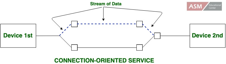
Connectionless-Service
In connectionless service, a router treats each packet individually. The packets are routed through different paths through the network according to the decisions made by routers. The network or communication channel does not guarantee data delivery from the host machine to the destination machine in connectionless service.
The data to be transmitted is broken into packets. These independent packets are called datagrams in analogy with telegrams.
The packets contain the address of the destination machine. Connectionless service is equivalent to the postal system. In the postal system, a letter is put in an envelope that contains the address of the destination. It is then placed in a letterbox.
The letter finally delivers to the destination through the postal network. However, it does not guarantee to appear in the addressee’s letterbox.
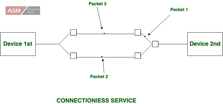
Differences
The major differences between connection oriented services and connectionless services in computer network are as follows−
Connection Oriented Services
It can generate an end to end connection between the senders to the receiver before sending the data over the same or multiple networks.
It generates a virtual path between the sender and the receiver.
It needed a higher bandwidth to transmit the data packets.
There is no congestion as it supports an end-to-end connection between sender and receiver during data transmission.
It is a more dependable connection service because it assures data packets transfer from one end to the other end with a connection.
Connectionless Services−
It can transfer the data packets between senders to the receiver without creating any connection.
It does not make any virtual connection or path between the sender and the receiver.
It requires low bandwidth to share the data packets.
There can be congestion due to not providing an end-to-end connection between the source and receiver to transmit data packets.
It is not a dependent connection service because it does not ensure the share of data packets from one end to another for supporting a connection.
Posted by Ajmal Ward & filed under CompTIA Network+, MICROSOFT MTA NETWORKING.
Simple Network Management Protocol (SNMP)
SNMP stands for Simple Network Management Protocol. It is an Internet-standard protocol for handling devices on IP networks. Devices that typically provide SNMP include routers, switches, servers, workstations, printers, modem racks, and more. It is used mainly in the network management framework to monitor network-attached computers for conditions requiring regulatory attention.
It is a framework for managing devices on the Internet using the TCP-IP protocol suite. It supports a set of fundamental operations for monitoring and maintaining the Internet.
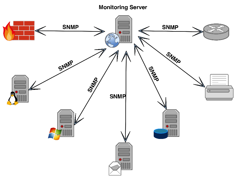
SNMP Concept
SNMP facilitates the concept of manager and agent. A manager, generally a host, controls and monitors a group of agents, usually routers. This is an application-level protocol in which some manager stations control a group of agents. The protocol is designed to monitor different manufacturer’s devices and installed on various physical networks at the application level.
Managers and Agents
A management station, known as a manager. It is a host that runs the SNMP user program. A managed station was known as an agent. It is a router (or a host) that runs the SNMP server program. Management is completed through simple interaction between a manager and an agent. The agent keeps performance data in a database. The manager has created the values in the database.
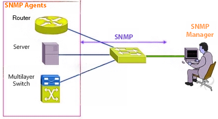
Components of SNMP
An SNMP-managed network includes three key components. These components are as follows −
- Managed Device− It is a network node that executes an SNMP interface that enables unidirectional (read-only) or bidirectional access to node-specific information.
- Agent− An agent is a network-management software mechanism that consists of a managed device. An agent has local knowledge of management data and translates that information to or from an SNMP specific form.
- Network management system (NMS)− A network management system (NMS) executes applications that monitor and control managed devices.
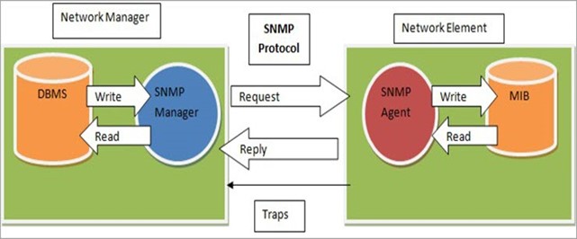
SNMP Protocols
SNMP uses two other protocols which are as follows –
SMI
SMI stands for Structure Management Information. SMI represents the general rules for naming objects, defining object types (including range and length), and showing how to encode objects and values.
SMI does not determine the number of objects an entity should handle or name the objects to be managed or define the relationship between the objects and their values.
MIB
MIB stands for Management information base. For each entity to be handled, this protocol must represent the number of objects, name them as per the rules represented by SMI, and relate a type to each named object. MIB generates a collection of named objects, their types, and their relationships to each other in an entity to be managed.
Source: www.tutorialspoint.com/what-is-the-snmp-in-the-computer-network
Images: From google images

Contact Us
* These fields are required.