Posted by & filed under CompTIA Network+, MICROSOFT MTA NETWORKING.

Dynamic Host Configuration Protocol (DHCP)

Dynamic Host Configuration Protocol (DHCP) is a client/server protocol that automatically provides an Internet Protocol (IP) host with its IP address and other related configuration information such as the subnet mask and default gateway. In DHCP, port number 67 is used for the server and 68 is used for the client.

DHCP allows a network administrator to supervise and distribute IP addresses from a central point and automatically sends a new Internet Protocol (IP) address when a computer is plugged into a different place in the network.

DHCP is an application layer protocol that provides −

  • Subnet Mask
  • Router Address
  • IP Address

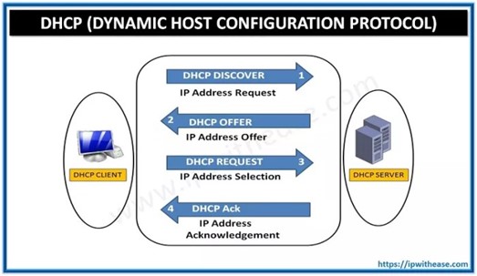
DHCP Client-Server Communication Diagram

In DHCP, the client and the server exchange DHCP messages to establish a connection.

DHCP Discover Message − Client Requests DHCP Information

  • It is the first message produced by a client in the communication process between the client and server with the target address 255.255.255.255 and the source address 0.0.0.0.
  • This message is produced by the client host to discover if there are any DHCP servers present in a network or not.
  • The message might contain other requests like subnet mask, domain name server, and domain name, etc.
  • The message is broadcast to all the devices in a network to find the DHCP server.
CompTIA Network+ Certification

DHCP Offer Message − DHCP Server Offers Information to Client

  • The DHCP server will reply/respond to the host in this message, specifying the unleashed IP address and other TCP configuration information.
  • This message is broadcasted by the server.
  • If there are more than one DHCP servers present in the network, then the client host accepts the first DHCP OFFER message it receives.
  • Also, a server ID is specified in the packet to identify the server.

DHCP Request Message − Client Accepts DHCP Server Offer

  • The Client receives the DHCP offer message from the DHCP server that replied/responded to the DHCP discover message.
  • After receiving the offer message, the client will compare the offer that is requested, and then select the server it wants to use.
  • The client sends the DHCP Request message to accept the offer, showing which server is selected.
  • Then this message is broadcast to the entire network to let all the DHCP servers know which server was selected.
CompTIA Network+ Certification

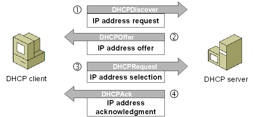
DHCP Acknowledgment Message − DHCP server acknowledges the client and leases the IP address.

  • If a server receives a DHCP Request message, the server marks the address as leased.
  • Servers that are not selected will return the offered addresses to their available pool.
  • Now, the selected server sends the client an acknowledgment (DHCP ASK), which contains additional configuration information.
  • The client may use the IP address and configuration parameters. It will use these settings till its lease expires or till the client sends a DHCP Release message to the server to end the lease.

DHCP Request, DHCP ACK Message − Client attempts to renew the lease

  • The client starts to renew a lease when half of the lease time has passed.
  • The client requests the renewal by sending a DHCP Request message to the server.
  • If the server accepts the request, it will send a DHC ACK message back to the client.
  • If the server does not respond to the request, the client might continue to use the IP address and configuration information until the lease expires.
  • As long as the lease is still active, the client and server do not need to go through the DHCP Discover and DHCP Request process.
  • When the lease has expired, the client must start over with the DHCP Discover process.
CompTIA Network+ Certification

The client ends the lease − DHCPRELEASE.

  • The client ends the lease by sending a DHCP Release message to the DHCP server.
  • The server will then return the client’s IP address to the available address pool and cancel any remaining lease time.

Posted by & filed under CompTIA Network+, MICROSOFT MTA NETWORKING.

CompTIA NET+ | Generic Routing Encapsulation (GRE)

Generic Routing Encapsulation (GRE) is a routing protocol developed by Cisco Systems in 1994 that allows a wide range of network-layer protocols to be contained inside virtual point-to-point or point-to multipoint links over an Internet Protocol network. Protocol encapsulation, not GRE specifically, breaks the layering sequence, according to the OSI principles of protocol layering.

GRE can be thought of as a barrier between two protocol stacks, one of which serves as a carrier for the other. IP protocol type 47 is used for GRE packets enclosed within IP. It is a tunneling protocol and is defined by RFC 2784. GRE provides both stateless and private connection.

GRE establishes a secure, stateless connection. The protocol establishes a connection that is comparable to that of a Virtual Private Network (VPN). Over an IP network, it can carry any OSI layer three protocol.

GRE establishes a tunnel between two routers over the Internet to allow communication between two hosts of different private networks. With the help of Virtual Tunnel Interface, the GRE connection endpoints can be terminated.

GRE Tunneling

GRE creates a private way for packets to travel through an otherwise public network by encapsulating or tunnelling the packets. Tunnel endpoints that encapsulate or de-encapsulate the traffic are used in GRE tunnelling.

Encapsulating packets within other packets is known as tunnelling. GRE tunnels are often set up between two routers, with each router acting as the tunnel’s end. The routers are configured to send and receive GRE packets directly.

Within an outer IP packet, GRE encapsulates a payload, an inner packet that must be transferred to a target network. GRE tunnel endpoints route encapsulated packets via intervening IP networks to convey payloads across GRE tunnels. GRE tunnels are used to connect different subnetworks.

CompTIA Network + Certification Boot Camp.

Advantages of GRE

  • IPv4 broadcast and multicast traffic can be encapsulated using the GRE protocol.
  • IPv6 is also supported.
  • It’s a straightforward and adaptable protocol.
  • Numerous protocols are encapsulated in a single GRE tunnel.
  • It can connect multiple discontinuous sub-networks and is easy to debug.
Comp TIA Network+ Certifications_GRE

Disadvantages of GRE

  • It does not provide a data encryption facility, and it needs to be integrated with other security protocols to provide network security.
  • Defining GRE tunnels is a laborious process; hence it is less scalable.

There are quite a few protocols available for data transfer via a secure network. Protocols were created for a reason, and they’re getting better all the time. Whether it’s greater security or ease of use and configuration, we always have various aspects to consider when picking the optimal protocol for a network.

Source: What
is Generic Routing Encapsulation (GRE) (tutorialspoint.com)

Pictures From: Image1, image2, image3, imageADV, imagedis.

Posted by & filed under CompTIA A+, MICROSOFT MTA O/S.

What are the Different Motherboard Form Factors?

Microsoft MTA O/S | CompTIA A+ Exam objectives 1.2: sizes.

Introduction to Motherboards

A motherboard (MB), also known as a Mainboard, system board or logic board, is the central or primary circuit board in a Personal Computer (PC). It is an extremely complex electronic system that every device in a computer system connects to in order to send and receive data. A typical motherboard is made up of a main microprocessor, called the CPU, two or more DIMM slots to hold memory modules, support chips called the Chipset, controller ports for connecting storage drives, expansion slots for adding connections, and integrated input and output ports for connecting external devices.


Also known as a mainboard, system board, mobo or MB, here’s how a motherboard looks like:


Motherboard Form Factors

Motherboard form factors refer to the layout, features, and size of a motherboard. While there are dozens of form factors for desktop computers, most of them are either obsolete or developed for specialized purposes.

As a result, almost all consumer motherboards sold today belong to one of these form factors: ATX, Micro-ATX, Mini-ITX and EATX

What Does Each One Mean?

To start, let’s begin with the “standard”-sized motherboard which is the ATX. ATX stands for “Advanced Technology eXtended” and was developed as far back as 1995. If you own, or have owned, a regular-sized PC, there’s a good chance it has an ATX motherboard. This makes ATX the “regular” choice when purchasing a PC or motherboard.

From ATX, motherboards get either bigger or smaller in size. Going upward, you have the EATX motherboard (Extended ATX) which adds more to the ATX board and is slightly larger as a result. Going the other way, you have the Micro ATX which is smaller than the ATX. After that is the Mini ITX (“Information Technology eXtended”) which is even smaller than the Micro ATX.

ATX

The most popular standard for PC motherboards is ATX, which stands for Advanced Technology Extended. ATX motherboards are considered to be full-size with up to seven PCI/PCI Express (PCIe) expansion slots. Expansion slots are needed for things like graphics cards, sound cards, NVMe PCIe Solid State Drives (SSDs), and various peripherals. They also provide up to eight slots for RAM.

MINI-ITX

If you need a computer that is really small then you should look to Mini-ITX. These boards are primarily used in small form factor (SFF) computer systems where the entire computer must fit in a cabinet or on a bookshelf or otherwise be very portable. Typical uses include home theater PCs (HTPCs) where low power consumption means less noise from cooling fans and LAN gaming where you need something that is easy to carry around. Many new CPUs include integrated graphics eliminating the need for a dedicated graphics card if you aren’t after high resolution and/or high frame rates. This is good, because the Mini-ITX standard allows for just one PCI expansion port. To take full advantage of the smaller form factor you may need to find something other than a standard ATX power supply as they are generally too large for small Mini-ITX cases.

EATX

On the other hand, if space is not your concern, but performance and reliability are then eATX is for you. The e stands for extended making this an Extended Advanced Technology Extended motherboard. Boy that’s a mouthful. Generally these are used for enterprise-class high-performance workstations and servers. While it’s the same height as an ATX motherboard, it is 86 mm (3.39 inches) wider. This additional space is generally used for a second CPU, but single CPU boards are also available. They also have eight memory slots and up to seven PCI expansion slots, but using an older 64-bit PCI standard called PCI-X (PCI Extended).

Micro ATX

As the computer Technology developed the computer market changed and demand of small and powerful main boards was huge in numbers. They were developed using the same ATX form Factor in mind as the price of this motherboard was low the demand Increased rapidly.

Pros and Cons of each form factor

Pros

Cons

ATX

  • Excellent overclocking potential
  • Easy to find compatible components
  • Usually features great aesthetics
  • Little expensive
  • Also requires a lot of space

Micro-ATX

  • Very affordable
  • Kinda Portable
  • Small enough for a on-desk setups
  • Decent overclocking
  • Lower at RAM capacity than ATX
  • Not ideal for Multi-GPU setups

Mini-ITX

  • Affordable
  • Very Portable (Ideal for LAN Parties
  • Makes great HTPC
  • Not a great choice for overclocking
  • Minimal RAM capacity
  • No Multi-GPU Support

EATX

  • Enthusiasts-Tier overclocking
  • More PCIe lanes
  • High Ram capacity
  • Ideal for 4-way GPU builds, servers and High-End workstations
  • Very expensive
  • Requires a lot of space

Motherboard Form Factor Comparison Chart

ATX

Micro ATX

EATX

Mini-ITX  

Maximum Size 

30.5 x 24.4 cm

12 x 9.6 in              

24.4 x 24.4 cm

9.6 x 9.6 in                 

30.48 x 33.02 cm

12 x 13 in            

.17 x 17 cm

6.7 x 6.7 in

Ram Slots  

2 to 8   

2 to 4            

8

2

RAM Type 

DIMM

DIMM .

DIMM

DIMM, SODIMM

Expansion Slots     

7

4

7  

1

Graphics Cards   

1 – 4          

1 – 3        

1-4

0-1

Expansion Slots     

4 – 12

4 – 8

4 – 12

2 – 6

Credits: Build Computers

Posted by & filed under CompTIA A+, MICROSOFT MTA O/S.

Backup and recovery procedures protect your data against data loss and reconstruct the data, should loss occur.

When searching for a backup solution, you’ll find that there are two main types of backups: “file-level backup” and “image-level backup.”

File-Level Backup

File-level backups are the most common type of backup. This method has been around for a long time, and most people are familiar with the process.  File level backup allows you to save individual files and folders from your office computer to a remote location. You’ve probably used a consumer-level backup program to save files, such as Google Drive, Dropbox, or Microsoft Office Drive. Because only changed data is saved with each backup, the total backup is smaller in size and therefore requires less storage space.

For most SMBs, operating only a few machines or in a home computing situation, this type of backup is usually adequate for maintaining your data. Delete a file? Go and get it from your external drive or cloud storage solution.

Image-Level Backup

Image-level backup is known by many names: bare metal backup/recovery (BMR), disaster recovery backup, ghost backup, block-level backup or “cloning” your machine. Image level backup is a more complete option for backing up your practice data. Rather than copying individual files and folders, image level backup takes a snapshot of your entire operating system and all of the data associated with it. The backup is saved in a single file called an image, which can be retrieved and restored if your practice suffers a major data loss. This backup method requires more storage space, but it’s much more efficient when you want to get back up and running as quickly as possible.

Another benefit of image level backup is that the copy of your operating system can be restored to any computer. So, if your hardware is damaged due to a fire or flood, or if your computers are stolen, there’s no need to search for and purchase compatible older machines. And, while the main benefit of image level backup is having the ability to quickly restore your entire server from a single file, it’s also possible to retrieve a singular file – eliminating the need for file level backups.

Learn more about our A+ certification.

Posted by & filed under CompTIA A+, MICROSOFT MTA O/S.

Source by Wikipedia

Monitor Connectors:

· If you are using a Monochrome / CGA/ EGA monitor, it is a digital monitor and will have a DB-9 Male connector that plugs into a digital adapter.
· If you are using a VGA/ SVGA monitor, it will have a male DB-15 connector that plugs into ananalog adapter. You should never interchange an analog monitor to that of a digital adapter and vice versa, or severe damage may take place.

Video types


Video monitor

Max. Color depth

Max. Resolution

CGA

16 Colors

160X100

EGA

64 colors

640X350 (Graphics Mode)

VGA

256 colors

640X480 (Graphics Mode)

SVGA

16 Million Colors

1280X1024 or even more

When you are installing a different SVGA monitor, it is unlikely that the new monitor has the same
capabilities as the old one. As a result, the image on the screen may not be readable. In such instances,
change the video resolution to Standard VGA before installing the new monitor. You can change the
resolution appropriately after the image on the screen is readable with the new monitor. It may also be
necessary to load appropriate device driver, if you are installing a different display adapter.

LCD Monitors:

The ‘native resolution’ specification points out one of the big differences between LCD and CRT
displays. If you run an LCD at any resolution other than its native resolution, the display will become
blurry, especially with text. The reason this happens on LCDs is that they are made up of tiny cells in a
matrix (called the native resolution). For instance, if the native resolution is listed as 1280×1024, then
there are 1280 cells across and 1024 cells down the screen. If you only display at 1024×768, then a
large number of the pixels are being ’stretched’ over multiple cells, which is what causes the image
quality to degrade.

Various resolutions commonly used with LCD monitors are as given below:
1024 x 768 is XGA (eXtended Graphics Array)
1280×720 is WGA/WXGA (Wide eXtended Graphics Array)
1280 x 1024 is SXGA (Super eXtended Graphics Array)
1400×1050 is SXGA+ (Super eXtended Graphics Array Plus)
1680×1050 is WSXGA (Wide Super eXtended Graphics Array Plus)
1600×1200 is UXGA (Ultra eXtended Graphics Array)
1920×1200 is WUXGA (Wide Ultra eXtended Graphics Array)

Wide screen format aspect ratio is typically 16:10 for computer monitors and 16:9 for LCD
televisions. Aspect ratio of 16:10 conforms with WUXGA standard. Further note that UXGA has a
resolution of 1600X1200 and an aspect ratio of 4:3.

Products or instrumentation equipped with a touch screen normally require a calibration routine upon
power up because it is difficult to perfectly align a touch screens coordinates with those of the display
underneath it. Calibration is necessary when the coordinates of the area touched on the screen are not
sufficiently close to the coordinates on the display. Without proper calibration, software may not
respond correctly when a soft button or icon is pressed.It is recommended that you clean the LCD
screen with clean water, using a soft cotton cloth. Do not spray water directly on the screen. First wet
the cloth (no dripping of water), and wipe the LCD screen gently.

Monitors and static charge:

1. Monitors accumulate very high static charges and need to be handled very carefully. Before
attempting any repair, it is important to discharge any accumulated charges on the monitor. You can
use a jumper, one end of which is grounded, and touch the other end of the jumper wire to the anode of
the monitor. While doing so, ensure that you are not in direct contact with the jumper wire or the
anode. You can use a screwdriver, or a nose pliers with rubber handle for this purpose. A “POP” sound
can be heard when the static charges accumulated on the anode lead getting grounded through the
jumper wire. Static charges accumulated on monitors may lead to severe burn or even fatal, if come
into direct contact.

2. Never wear a wrist strap when working on monitors. Monitors contain very high voltages,
sometimes fatal to human, even when the power is turned off. If you are wearing wrist strap, the
human body works as a conduit to discharge the electric charge.

Want more information on how to become CompTIA A+ Certified? Learn more!

Posted by & filed under CompTIA A+, MICROSOFT MTA O/S.

Source by Wikipedia

A bus is a set of signal pathways that allow information to travel between components inside or outside of a computer.

Laptop Buses

PCMCIA or PC Card

Personal Computer memory card international association is a type of bus use for laptops. There are different types of cards and you primarily slide in the card in a PC card slot of a laptop.

Type II PCMCIA Card

PC Card Types

Measurement

Usage

Type I

3.3mm

Flash Memory

Type II

5.0mm

USB/NIC/Wireless

Type III

10.5mm

Hard Drive

Note: PCMCIA (Personal Computer Memory Card International Association) cards supports 16 or 32 bit bus width.

Express Card

Express Card is the newest form of card you insert in newer laptops

List of Ports

Computer ports are connection points or interfaces with other peripheral devices. There are two main types of computer ports: physical and virtual.
Physical ports are used for connecting a computer trough a cable and a socket to a peripheral device. Physical computer ports list includes serial ports ( DB9 socket ), USB ports ( USB 2.0 or 3.0 socket / connector ), parallel ports ( DB25 socket / connector ), ethernet / internet ports ( RJ45 socket / connector )….

In this day’s most desktop and notebook computers use only USB, VGA, Ethernet, IEEE 1394, DVI and TRS physical ports. Serial, parallel, PS/2 and SCSI are used more by industrial and professional computers.

Phisical common computer ports – short description

-USB port (Universal Serial Bus) created in mid-1990’s mainly to standardize communications between computers and peripheral. Also, USB ports can be used as a power supply for different devices like digital cameras, microcontroller programmers, laptop coolers and other. There were four types of USB computer ports: USB1.0 and 1.1 released between 1996 and 1998 with a speed range starting from 1.5 Mb up to 12 Mb; USB 2.0 released in 2000 with a maximum speed of 480 Mb/sec and USB 3.0 released in 2008 with a maximum speed of 5 Gb/sec.

-Ethernet/internet ports were first introduced in 1980 to standardize the local area networks (LAN). Internet ports use RJ45 connectors and have speeds between 10 Mb/sec, 100 Mb/sec and 1 Gb/sec, 40 Gb/sec and 100 Gb/sec
VGA ports (Video Graphics Array) has 15 pins displayed on three rows and it is mainly used for connecting the monitor with the video adapter from the computer motherboard; adapters:
·HDMI (High-Definition Multimedia Interface)
·DVI (Digital Visual Interface)

-IEEE 1394 ports this technology is developed by Apple between 1980 and 1990 with the name FireWire and it is the equivalent of the USB for Apple computers

-IEEE 1284 ports Printers – Parallel Communication Standard

-TRS (Tip, Ring, and Sleeve) ports are used for receiving and transmitting with analog signals like audio

-DVI are computer ports used to transmit uncompressed digital video data

-PS/2 ports were introduced in 1987 to replace the serial mouse and keyboard

-Serial port uses the DB9 socket/connector and transfers information, one bit at a time, between the computer and other peripherals. The serial computer port identifies with RS-232 standard

Want more information on how to become CompTIA A+ Certified? Learn more!

Posted by & filed under CompTIA A+, MICROSOFT MTA O/S.

Source by Wikipedia

A bus is a set of signal pathways that allow information to travel between components inside or outside of a computer.

Other Types of Bus

USB

USB or Universal Serial Bus is an external bus that most popular form of bus use today
USB is hot swappable
USB can daisy-chain up to 127 devices

USB Speeds
USB 1.0 supports 1.5Mbps
USB 1.1 supports 12Mbps
USB 2.0 supports up to 480Mbps
USB 3.0 supports up to 4.8Gbps


USB_A Connector

USB_B Connector

AMR

Released September 8, 1998, AMR is short for Audio/Modem Riser. AMR allows an OEM to create one card that has the functionality of either Modem or Audio or both Audio and Modem on one card. This new specification allows for the motherboard to be manufactured at a lower cost and free up industry standard expansion slots in the system for other additional plug-in peripherals.

AMR Slot

CNR

Introduced by Intel February 7, 2000, CNR is short for Communication and Network Riser and is a specification that supports audio, modem USB and Local Area Networking interfaces of core logic chipsets.

CNR Slot

PCI-X

PCI-X is a high-performance bus that is designed to meet the increased I/O demands of technologies such as Fibre Channel, Gigabit Ethernet, and Ultra3 SCSI.

PCI-X card

PCI-X Slots


Type of Bus

Bits Wide

Clock Speed

Transfer Speed

PCI-X (v1)

64bit

66MHz * 8 =

528MB/s

PCI-X (v1)

64bit

100MHz * 8 =

800MB/s

PCI-X (v1)

64bit

133MHz * 8 =

1066MB/s


PCI Express

A high-speed serial I/O interconnect standard being used for high-speed connection it will eventually replace the PCI standards

PCI-e Card

Lane Widths

Peak unidirectional bandwidth

Peak full duplex bandwidth

x1

250MB/s

500MB/s

x2

500MB/s

1GB/s

x4

1GB/s

2GB/s

x8

2GB/s

4GB/s

x16

4GB/s

8GB/s

Want more information on how to become CompTIA A+ Certified? Learn more!

Posted by & filed under CompTIA A+, MICROSOFT MTA O/S.


Source by Wikipedia

A bus is a set of signal pathways that allow information to travel between components inside or outside of a computer.


Types of Bus


External bus or Expansion bus allows the CPU to talk to the other devices in the computer and vice versa. It is called that because it’s external to the CPU.


Address bus allows the CPU to talk to a device. It will select the particular memory address that the device is using and use the address bus to write to that particular address.


Data bus allows the device to send information back to the CPU


Types of Expansion Buses


ISA

Introduced by IBM, ISA orIndustry Standard Architecture was originally an 8-bit bus and later expanded to a 16-bit bus in 1984. When this bus was originally released it was a proprietary bus, which allowed only IBM to create peripherals and the actual interface. Later however in the early 1980’s, the bus was being created by other clone manufacturers.


16bit ISA Card

16bit ISA Slot


PCI


Introduced by Intel in 1992, PCI is short for Peripheral Component Interconnect and is a 32-bit or 64-bit expansion bus.


The PCI bus is the most popular expansion bus use in today’s computers.


PCI Card


PCI Slot


AGP


Introduced by Intel in 1997, AGP or Advanced Graphic Port is a 32-bit bus or 64-bit bus designed for the high demands of 3-D graphics. AGP has a direct line to the computers memory which allows 3-D elements to be stored in the system memory instead of the video memory.
AGP is one of the fastest expansion bus in use but it”s only for video or graphics environment.


AGP Card


AGP Slot


Expansion Bus Chart:

Type of Bus

Bits Wide

Clock Speed

Transfer Speed

ISA

8 bit

4.77 MHz

2.38MB/s

ISA

16 bit

8.33 MHz

8MB/s

PCI (Client)

64 bit

66MHz

266MB/s

AGP 1x

32 bit

66MHz

266MB/s

AGP 2x

32 bit

66MHz

533MB/s

AGP 4x

32 bit

66MHz

1,066MB/s

AGP 8x

32 bit

66MHz

2,133MB/s

AGP 8x (high-end)

64 bit

66MHz

4,266MB/s

Want more information on how to become CompTIA A+ Certified? Learn more!

Posted by & filed under CompTIA A+, CompTIA Network+, MICROSOFT MTA NETWORKING, MICROSOFT MTA O/S.


ComputerCableStore


When talking about cable pinouts we often get questions as to the difference in Straight-through, Crossover, and Rollover wiring of cables and the intended use for each type of cable. These terms are referring to the way the cables are wired (which pin on one end is connected to which pin on the other end). Below we will try shed some light on this commonly confused subject.


Straight-Through Wired Cables

Straight-Through refers to cables that have the pin assignments on each end of the cable. In other words Pin 1 connector A goes to Pin 1 on connector B, Pin 2 to Pin 2 ect. Straight-Through wired cables are most commonly used to connect a host to client. When we talk about cat5e patch cables, the Straight-Through wired cat5e patch cable is used to connect computers, printers and other network client devices to the router switch or hub (the host device in this instance).


 Connector A  Connector B
 Pin 1  Pin 1
 Pin 2  Pin 2
 Pin 3  Pin 3
 Pin 4  Pin 4
 Pin 5  Pin 5
 Pin 6  Pin 6
 Pin 7  Pin 7
 Pin 8  Pin 8


Crossover Wired Cables

Crossover wired cables (commonly called crossover cables) are very much like Straight-Through cables with the exception that TX and RX lines are crossed (they are at oposite positions on either end of the cable. Using the 568-B standard as an example below you will see that Pin 1 on connector A goes to Pin 3 on connector B. Pin 2 on connector A goes to Pin 6 on connector B ect. Crossover cables are most commonly used to connect two hosts directly. Examples would be connecting a computer directly to another computer, connecting a switch directly to another switch, or connecting a router to a router.Note: While in the past when connecting two host devices directly a crossover cable was required. Now days most devices have auto sensing technology that detects the cable and device and crosses pairs when needed.

 Connector A  Connector B
 Pin 1  Pin 1
 Pin 2  Pin 2
 Pin 3  Pin 3
 Pin 4  Pin 4
 Pin 5  Pin 5
 Pin 6  Pin 6
 Pin 7  Pin 7
 Pin 8  Pin 8


Rollover Wired Cables

Rollover wired cables most commonly called rollover cables, have opposite Pin assignments on each end of the cable or in other words it is “rolled over”. Pin 1 of connector A would be connected to Pin 8 of connector B. Pin 2 of connector A would be connected to Pin 7 of connector B and so on. Rollover cables, sometimes referred to as Yost cables are most commonly used to connect to a devices console port to make programming changes to the device. Unlike crossover and straight-wired cables, rollover cables are not intended to carry data but instead create an interface with the device.


 Connector A  Connector B
Pin 1  Pin 1
Pin 2 Pin 2
Pin 3 Pin 3
Pin 4 Pin 4
Pin 5 Pin 5
Pin 6 Pin 6
Pin 7 Pin 7
Pin 8 Pin 8


Want more information on how to become CompTIA A+ Certified? Learn more!


Posted by & filed under CompTIA A+, MICROSOFT MTA O/S.

Source Quizlet


What are three common problem areas with laptops?

  • Displays
  • Storage devices and RAM
  • Power and input devices


What are the three possible areas that a technician must check for printer errors?

  • The device
  • Cable connection
  • The computer to witch it is attached


What are some common causes of printer problems?

  • Loose cable connections
  • Paper jams
  • Equipment power
  • Low ink warning
  • Out of paper
  • Errors on equipment display
  • Errors on computer screen
  • Empty toner cartridge
  • Printer server is not working
  • The printer can not establish a connection to the wireless network


What are two probable causes of printer paper jams?

  • The wrong paper type is being used
  • Humidity causes the paper to stick together


What is a common cause of creases on paper when printed?

The pickup rollers are obstructed, damaged or dirty


What is the purpose of the first lab?

To reinforce your troubleshooting skills


What is the purpose of the second lab?

To reinforce your communication and troubleshooting skills with printers


What is the purpose of the third, fourth and fifth labs?

To reinforce your skills with printer problems


Define troubleshooting in the context of security

To be able to analyze a security threat and determine the appropriate method to protect assets and repair damage


What are some common causes of security problems?

  • The user account is disabled
  • The user is using an incorrect username or password
  • The user does not have the correct folder or file permissions
  • The firewall configurations are incorrect
  • The users computer has been infected by a virus
  • The wireless security configurations are incorrect on the client
  • The security configurations are incorrect on the wireless access point


What are some symptoms of malware infections?

  • Message MBR has been changed or modified appears at bootup
  • A windows 7 or windows vista computer starts with the error message “error loading operating system”
  • A windows 7 or windows vista computer starts with the error message “Caution: this hard disk may be infected by virus”
  • A windows xp computer will nto boot
  • A windows 7 computer will nto boot
  • Your contacts are receiving spam from your email account


What is the purpose of the first lab?

To test your troubleshooting skills with security problems


What is the purpose of the second lab?

To reinforce your communication and troubleshooting skills


What is the purpose of the third, fourth and fifth labs?

To rest you troubleshooting skills with security problems


What advanced troubleshooting topics were covered in this chapter?

  • Computer components
  • Peripherals
  • Operating systems
  • Networks
  • Laptops
  • Printers
  • Security


Click here to see more!


Want more information on how to become CompTIA A+ Certified? Learn more!


Posted by & filed under CompTIA A+, MICROSOFT MTA O/S.

Source Quizlet


Most often, what is the reason for a need for advanced troubleshooting?

It means that the probable cause is difficult to diagnose


What are the six steps of troubleshooting?

  • Identify the problem
  • Establish a theory of probable cause
  • Test the theory to determine the cause
  • Establish a plan of action to resolve the problem and implement the solution
  • Verify full system functionality and if applicable, implement preventative measures
  • Document findings, action and outcomes


What are the nine common advanced problems that occur with computers and peripherals?

  • An OS not found error message is displayed when the computer is started
  • RAID cannot be found
  • RAID stops working
  • The computer does not recognize a SCSI drive
  • The computer does not recognize a removable external drive
  • After updating the CMOS frimware the computer will not start
  • The computer reboots without warning, locks up, or displays error message, or the BSOD
  • The computer exhibits slow performance
  • After upgrading from a single core to a dual core CPU the computer runs slower and only shows one CPU graph in the task manager


What are the three steps designed to reinforce communication and troubleshooting skills?

  • Receive the work order
  • Talk the customer through various steps to try and resolve the problem
  • Document the problem and the resolution


When working to identify the problem with operating systems, what are three good open ended questions to ask the user?

  • What OS is installed on the computer?
  • What programs have been installed recently?
  • What updates or service packs have been installed?


What are three good close ended questions to ask when working to identify operating system problems?

  • Does anyone else have this problem?
  • Has this problem happened before?
  • Have you made any changes to you computer?


What are eight common causes of operating system problems?

  • Corrupted or missing system files
  • Incorrect device driver
  • Failed update or service pack installation
  • Corrupted registry
  • Failed or faulty hard drive
  • Incorrect password
  • Virus infection
  • Spyware


What are a few common steps in determining the cause in operating system problems?

  • Reboot the computer
  • Examine event logs
  • Run SFC/ScanNow
  • Roll back or reinstall the device driver
  • Uninstall recent updates or service packs
  • Run system restore
  • Run CHKDSK
  • Log in as a different user
  • Boot to the last known good configuration
  • Run a virus scan
  • Run a spyware scan


What are some steps to take if further research is needed to solve the problem?

  • Helpdesk repair logs
  • Other technicians
  • Manufacturer FAQ’s
  • Technical websites
  • Newgroups
  • Computer manuals
  • Device manuals
  • Online forums
  • Internet search


What are some steps to take in order to verify the solution and full system functionality?

  • Reboot the computer
  • Access all drives and shared resources
  • Check event logs to ensure there are no new warnings or errors
  • Check device manager to ensure there are no warnings or errors
  • Make sure applications run properly
  • Make sure the internet can be accessed
  • Check task manager to ensure that there are no unidentified programs running


What actions constitute documenting findings after a solution is found and systems tested?

  • Discuss the solution implemented with the customer
  • Have the customer verify the problem has been solved
  • Provide the customer with all the paper work
  • Document any components used in the repair
  • Document the time spent to resolve the problem


Most often, what is the reason for a need for advanced troubleshooting?

Operating system problems, hardware, software, networks or some combination of the three


What is a stop error?

A hardware or software malfunction that causes the system to lock up


What is a BSOD and what is usually the cause?

Black screen of death, device driver errors


What are some ways to prevent stop errors and BSOD?

  • Verify that the hardware and software drivers are compatible
  • Install the latest patches and update for windows
  • Event log and other diagnostic utilities


What is the purpose of the first lab?

Designed to reinforce your skills with the operating system


What is the purpose of the second lab?

Designed to reinforce your communication and troubleshooting skills


What is the purpose of the third, fourth and fifth labs?

Designed to reinforce you skills with operating system problems


What are a few step 3 quick procedures that can determine the exact cause or even a correct a network problem?

  • Restart the network equipment
  • Renew the IP address
  • Reconnect all of the network cables
  • Verify the wireless router configuration
  • Ping the local host
  • Ping the default gateway
  • Ping an external website
  • Verify the network equipment settings


What are three common causes of network connectivity problems?

  • Incorrect IP information
  • Incorrect wireless configuration
  • Disabled network connection


What are three common causes of not being able to send or receive email?

  • Incorrect email software settings
  • Firewall settings
  • Hardware connectivity issues


What are two common causes of transfer problems between FTP clients and servers?

  • Incorrect IP address and post settings
  • Security policies


What are two common causes of secure internet connection problems?

  • Incorrect certificate settings
  • Ports blocked by software and hardware


What are three common causes of unexpected information reported from CLI commands?

  • Incorrect IP address settings
  • Hardware connection issues
  • Firewall settings


What is the purpose of the second lab?

To reinforce your communication and troubleshooting skills


What is the purpose of the third, fourth and fifth labs?

To test your troubleshooting skills with networking problems


What are a few common causes of problems with laptops?

  • Laptop battery does not have a charge
  • Laptop battery will not charge
  • Loose cable connections
  • The inverter does not work
  • External keyboard does not work
  • Num lock is on
  • Loose RAM
  • A Fn key has disabled a capability
  • A button or slide switch has disabled the wireless connection]


What does the technician need to be sure to do when replacing components on laptops?

They they have the correct replacements and tools recommended by the manufacturer


Click here to see more!


Want more information on how to become CompTIA A+ Certified? Learn more!


Posted by & filed under CompTIA A+, MICROSOFT MTA O/S.

Source Learning About Computers


What are binary numbers? The binary number system is when only two numbers are used – 0 and 1. It is also called base 2. The computer number system is base 2. Our number system is referred to as decimal or base 10 because we use 10 digits (0 – 9) to form all of our numbers. There are many other number bases, including hexadecimal, but it’s easier for computers to utilize 0s and 1s.

In electronics, a 0 is off (usually 0 Volts) and 1 is on (usually 5 Volts). All computer data is composed of 1s and 0s. Each individual 1 or 0 is a bit. Four bits is a nibble. Eight bits is a byte. From there we have kilobytes, megabytes, etc. Since everything is a series of 1s and 0s, the CPU has to perform every calculation in binary. But before any operations are done, numbers have to first be converted into base 2.

But before diving into the binary number system and conversions, let’s first see how things work in our decimal system.

Let’s just pick a number…like 9345. How do we get this? Remember when I mentioned we use base 10? In math the base is a number that’s raised to a power (another name for power is exponent). For example 34 is 3 raised to the 4th power, which means you multiply 3 times itself 4 times (3 * 3 * 3 * 3).

We have what’s called a place value system. Each individual number holds a particular numerical position. We get these positions by using 10 raised to different powers. Start with the number on the right.

So looking at 9345, the right-most number 5 is in the ones place (10º = 1). The 4 is in the tens place (10¹ = 10). The 3 is in the hundreds place (10² = 100), and the 9 is in the thousands place (10³ = 1000). This is true for any number. Now the larger the number the more place values (ten thousands, hundred thousands, etc.), but I’m keeping it short in this example. So we have:


If you take each number, multiply it by its place value, & add the results, you get 9345.


Note: any number raised to 0 = 1. Any number raised to 1 = itself.

This method is used in base 2 except rather than the ones place, tens place, hundreds place, thousands place, etc. you have: ones place (2º), twos place (2¹), fours place (2²), and eights place (2³), etc.

Using the base 10 example just above, the number 10112 is like this:


It’s the same process for any number system. And remember, the computer number system always uses binary. So now that you have a basic understanding of place values, it’s time to start converting!


Converting From Binary To Decimal:
Converting binary to decimal is really quite simple. All you do is apply the same technique used in the place value illustration on the intro page except this time we will be using a 2 instead of a 10.

For example if we want to know what 1101000112 is in our number system (base 10) we do the following:


We usually start on the right. With each number, you raise 2 to its power then multiply the result by the binary digit. When you’re done, add all the results together and that is the number in base 10.


This method is used for converting any number base to decimal.


Decimal to Binary Conversion:
Decimal to binary conversion is not hard either, it just takes a little more work. There are two methods you can use: successive division and subtracting values using a table.

Successive division requires dividing continuously by the base you’re converting to until the quotient equals 0. The remainders compose the answer.

As an example, let’s convert 835 to binary.


The most significant bit is the left number in the answer and the least significant bit is on the right end giving us an answer of: 11010000112

Binary digits are usually grouped by 4, 8, 16, etc. so we can place a couple of 0s on the left to give us three groups of four. This does not change the answer.

0011   0100   00112

You can check your answer by converting back to base 10.

We just looked at the successive division method of converting from decimal to binary. The other method is subtracting values. With this method you keep subtracting until you reach 0. Let’s convert 165 to binary.


Notice a 1 is only placed under the highest value that can be subtracted from a number. Everything else is automatically a 0 giving us an answer of: 101001012.

Hexadecimal:
The hexadecimal (hex for short) number system uses 16 digits to form all other numbers. The purpose of using hex is for human understanding. Computers always work in binary (0s and 1s). To have a long series of binary digits gets complicated, so programmers had to come up with a more simplfied way to represent them. Hex groups binary numbers into 4 bit packages so to speak. One hex digit represents four bits (called a nibble). Hexadecimal numbers have a subscript 16 or H behind them (D316 or D3H). Because single characters must be used, the letters A, B, C, D, E, F represent 10-15. Remember, when dealing with number systems, we always start with 0. So we have 0, 1, 2, 3, 4, 5, 6, 7, 8, 9, A, B, C, D, E, F. Memory locations are listed as hex values, and many times when you get an error message, your OS (operating system) will show you the location.

Example of hex and the number of bits:

F6AH – 12 bits
BH – 4 bits
78H – 6 bits


Converting Hexadecimal to Decimal:
As was mentioned in the binary conversion section above, we use the same technique to convert to decimal (base 10) from any other base. In this case, let’s convert 4B7F16 to Base 10 (decimal).


Converting Decimal to Hexadecimal:
To convert from decimal to hexadecimal, we use the successive division method discussed earlier only we divide by 16 instead of 2. Let’s convert 501 from decimal to hex.


We’re done since we can’t divide 1 by 16 and that leaves us with a remainder of 1. When writing the answer the LSD is always on the right and the MSD on the left. The answer is: 1F516

Converting Hexadecimal to Binary:
Remember hex uses groups of four bits, so we can use the table below for conversions.

Decimal Binary Hex
0 0000 0
1 0001 1
2 0010 2
3 0011 3
4 0100 4
5 0101 5
6 0110 6
7 0111 7
8 1000 8
9 1001 9
10 1010 A
11 1011 B
12 1100 C
13 1101 D
14 1110 E
15 1111 F

To convert D14B to binary:

D = 1101, 1 = 0001, 4 = 0100, B = 1011

When we put the pieces together, we get: D14B16 = 11010001010010112


Converting Binary to Hexadecimal:
To convert 11110101010011102 to base 16, we first break up the number into groups of four as shown below:

1111 0101 0100 1110

Now assign each group its corresponding hex value

1111 = F, 0101 = 5, 0100 = 4, 1110 = 14

When put together, we get F54E16


Want more information on how to become CompTIA A+ Certified? Learn more!


Posted by & filed under CompTIA A+, MICROSOFT MTA O/S.

Source Learning About Computers

To install a power supply is really quite easy. It fits in the top back of the case. First, orient the holes on the power supply to those on the case.

Then, place the unit in the space provided and slide it in until the screw holes are aligned.

Secure it by screwing it in.

Finally, plug the power connector into the motherboard. It connects one way.

Want more information on how to become CompTIA A+ Certified? Learn more!

Posted by & filed under CompTIA A+, MICROSOFT MTA O/S.

Source: Adopted From www.computerhope.com

Almost all laptops can connect to an external display and have the laptop display sent to that external display instead of, or in addition to, the laptop screen. Examples of an external display include a CRT monitor, flat panel display, projector, or TV. Read more »

Posted by & filed under CompTIA A+, MICROSOFT MTA O/S.

Source: Adopted From www.computerhope.com

Unlike a desktop computer, laptops and other portable computers often do not offer many upgrade options. Below is a listing of common laptop upgrade questions and the answers to each of the questions regarding laptop and portable computer upgrades. Read more »

Posted by & filed under CompTIA A+, MICROSOFT MTA O/S.

A bad computer motherboard or CPU can cause an assortment of different issues on your computer. Below are just a few of the possible issues you may encounter. It is important to remember that the issues below can also be caused by more than just a bad motherboard and CPU. Read more »