
No feed items found.


No feed items found.
No feed items found.
No feed items found.

2 Taft Court, Rockville, MD (map)


[bs_icon name=”glyphicon glyphicon-collapse-down”] We look forward to serving people at women’s Shelter located in Rockville, MD. Please join us on 2nd Sunday of each month at 2 Taft court , Rockville MD .
2 Taft Court, Rockville, MD (map)
[bs_icon name=”glyphicon glyphicon-collapse-down”] We look forward to serving people at women’s Shelter located in Rockville , MD. Please join us on 2nd Sunday of each month at 2 Taft court , Rockville MD .
2 Taft Court, Rockville, MD (map)


[bs_icon name=”glyphicon glyphicon-collapse-down”] It was a blessings night to serve about 35 people at women’s Shelter located in Rockville , MD. Please join us on 2nd Sunday of each month at 2 Taft court , Rockville MD .
Question
6) A web application allows customers to upload orders to an S3 bucket. The resulting Amazon S3 events trigger a Lambda function that inserts a message to an SQS queue. A singleEC2 instance reads messages from the queue, processes them, and stores them in an DynamoDB table partitioned by unique order ID. Next month traffic is expected to increase by a factor of 10 and a Solutions Architect is reviewing the architecture for possible scaling problems.Which component is MOST likely to need re-architecting to be able to scale to accommodate the new traffic?
A.Lambda function
B.SQS queue
C.EC2 instance
D.DynamoDB table
7) An application saves the logsto an S3 bucket. A user wants to keep the logs forone month for troubleshooting purposes, and then purge the logs. What feature will enable this?
A.Adding a bucket policy on the S3 bucket.
B.Configuring lifecycle configuration rules on the S3 bucket.
C.Creating an IAM policy for the S3 bucket.
D.Enabling CORS on the S3 bucket.
8) An application running on EC2 instances processes sensitive information stored on Amazon S3. The information is accessed over the Internet. The security team is concerned that the Internet connectivity to Amazon S3 is a security risk.Which solution will resolve the security concern?
A.Access the data through an Internet Gateway.
B.Access the data through a VPN connection.
C.Access the data through a NAT Gateway.
D.Access the data through a VPC endpoint for Amazon S3.
9) An organization is building an Amazon Redshift cluster in their shared services VPC. The cluster will host sensitive data.How can the organization control which networks can access the cluster?
A.Run the cluster in a different VPC and connect through VPC peering.
B.Create a database user inside the Amazon Redshift cluster only for users on the network.
C.Define a cluster security group for the cluster that allows access from the allowed networks.
D.Only allow access to networks that connect with the shared services network via VPN.
10) A Solutions Architect is designing an online shopping application running in a VPC on EC2 instances behind an ELB Application Load Balancer.The instances run in an Auto Scaling group across multiple Availability Zones. The application tiermust read and write data to a customer managed database cluster. There should be no access to the database from the Internet, but the cluster must be able to obtain software patches from the Internet.Which VPC design meets these requirements?
A.Public subnets for both the application tier and the database cluster.
B.Public subnets for the application tier, and private subnets for the database cluster.
C.Public subnets for the application tier and NAT Gateway, and private subnets for the database cluster.
D.Public subnets for the application tier, and private subnets for the database cluster and NAT Gateway.
Answers
6) C –Asingle EC2 instance will not scale and is a single point of failure in the architecture. A much better solution would be to have EC2 instances in an Auto Scaling group across 2 availability zones read messages from the queue. The other responses are all managed services that can be configured to scale or will scale automatically. For more information Click here
7) B –Lifecycle configuration allows lifecycle management of objects in a bucket. The configuration is a set of one or more rules, where each rule defines an action for Amazon S3 to apply to a group of objects. Bucket policies and IAM define access to objects in an S3 bucket. CORS enables clients in one domain to interact with resources in a different domain.
8) D –VPC endpoints for Amazon S3 provide secure connections to S3 buckets that do not require a gateway or NAT instances. NAT Gateways and Internet Gateways still route traffic over the Internet to the public endpoint for Amazon S3. There is no way to connect to Amazon S3 via VPN. For more information Click here
9) C –A security group can grant access to traffic from the allowed networks via the CIDR range for each network. VPC peering and VPN are connectivity services and cannot control traffic for security. Amazon Redshift user accounts address authentication and authorization at the user level and have no control over network traffic. For more information Click here
10) C –The online application must be inpublic subnets to allow access from clients’ browsers. The database cluster must be in private subnets to meet the requirement that there be no access from the Internet. For more information Click here
Source: Amazon
Question
1) A company is storing an access key (access key ID and secret access key) in a text file on a custom AMI. The company uses the access key to access DynamoDBtables from instances created from the AMI. The security team has mandated a more secure solution.Which solution will meet the security team’s mandate?
A.Put the access key in an S3 bucket, and retrieve the access key on boot from the instance.
B.Pass theaccess key to the instances through instance user data.
C.Obtain the access key from a key server launched in a private subnet.
D.Create an IAM role with permissions to access the table, and launch all instances with the new role.
2) A company is developing a highly available web application using stateless web servers. Which services are suitable for storing session state data?(Select TWO.)
A.CloudWatch
B.DynamoDB
C.Elastic Load Balancing
D.ElastiCache
E.Storage Gateway
3) Company salespeople upload their sales figures daily.
A Solutions Architect needs a durable storage solution for these documents that also protects against users accidentally deleting important documents. Which action will protect against unintended user actions?
A.Store data in an EBS volume and create snapshots once a week.
B.Store data in an S3 bucket and enable versioning.
C.Store data in two S3 buckets in different AWS regions.
D.Store data on EC2 instance storage.
4) An application requires a highly available relational database with an initial storage capacity of 8 TB. The database will grow by 8 GB every day. To support expected traffic, at least eight read replicas will be required to handle database reads.Which option will meet these requirements?
A.DynamoDB
B.Amazon S3
C.Amazon Aurora
D.Amazon Redshift
5) A Solutions Architect is designing a critical business application with a relational database that runs on an EC2 instance. It requires a single EBS volume that can support up to 16,000 IOPS.
Which Amazon EBS volume typecan meet the performance requirements of this application?
A.EBS Provisioned IOPS SSD
B.EBS Throughput Optimized HDD
C.EBS General Purpose SSD
D.EBS Cold HDD
Answers
1) D–IAM roles for EC2 instances allow applications running on the instance to access AWS resources without having to create and store any access keys. Any solution involving the creation of an access key then introduces the complexity of managing that secret. For more information click here.
2) B, D –Both DynamoDB and ElastiCache provide high performance storage of key-value pairs. CloudWatch and ELB are not storage services. Storage Gateway is a storage service, but it is a hybrid storage service that enables on-premises applications to use cloud storage.
3) B –If a versioned object is deleted, then it can still be recovered by retrieving the final version. Response A would lose any changes committed since the previous snapshot. Storing the data in 2 S3 buckets would provide slightly more protection, but a user could still delete the object from both buckets. EC2 instance storage is ephemeral and should never be used for data requiring durability. For more information click here.
4) C –Amazon Aurora is a relational database that will automatically scale to accommodate data growth. Amazon Redshift does not support read replicas and will not automatically scale. DynamoDB is a NoSQL service, not a relational database. Amazon S3 is object storage, not a relational database.
5) A –EBS Provisioned IOPS SSD provides sustained performance for mission-critical low-latency workloads. EBS General Purpose SSD can provide bursts of performance up to 3,000 IOPS and have a maximum baseline performance of 10,000 IOPS for volume sizes greater than 3.3 TB. The 2 HDD options are lower cost, high throughput volumes.
Source: Amazon
1) Why is AWS more economical than traditional data centers for applications with varying compute workloads?
A) Amazon Elastic Compute Cloud (Amazon EC2) costs are billed on a monthly basis.
B) Customers retain full administrative access to their Amazon EC2 instances.
C) Amazon EC2 instances can be launched on-demand when needed.
D) Customers can permanently run enough instances to handle peak workloads.
2) Which AWS service would simplify migration of a database to AWS?
A) AWS Storage Gateway
B) AWS Database Migration Service (AWS DMS)
C) Amazon Elastic Compute Cloud (Amazon EC2)
D) Amazon AppStream 2.0
3) Which AWS offering enables customers to find, buy, and immediately start using software solutions in their AWS environment?
A) AWS Config
B) AWS OpsWorks
C) AWS SDK
D) AWS Marketplace
4) Which AWS networking service enables a company to create a virtual network within AWS?
A) AWS Config
B) Amazon Route 53
C) AWS Direct Connect
D) Amazon Virtual Private Cloud (Amazon VPC)
5) Which of the following is AWS’s responsibility under the AWS shared responsibility model?
A) Configuring third-party applications
B) Maintaining physical hardware
C) Securing application access and data
D) Managing custom Amazon Machine Images (AMIs)
6) Which component of AWS global infrastructure does Amazon CloudFront use to ensure low-latency delivery?
A) AWS Regions
B) AWS edge locations
C) AWS Availability Zones
D) Amazon Virtual Private Cloud (Amazon VPC)
7) How would a system administrator add an additional layer of login security to a user’s AWS Management Console?
A) Use AWS Cloud Directory
B) Audit AWS Identity and Access Management (IAM) roles
C) Enable Multi-Factor Authentication
D) Enable AWS CloudTrail
8) Which service can identify the user that made the API call when an Amazon Elastic Compute Cloud (Amazon EC2) instance is terminated?
A) Amazon CloudWatch
B) AWS CloudTrail
C) AWS X-Ray
D) AWS Identity and Access Management (AWS IAM)
9) Which service would you use to send alerts based on Amazon CloudWatch alarms?
A) Amazon Simple Notification Service (Amazon SNS)
B) AWS CloudTrail
C) AWS Trusted Advisor
D) Amazon Route 53
10) Where can a customer find information about prohibited actions on AWS infrastructure?
A) AWS Trusted Advisor
B) AWS Identity and Access Management (IAM)
C) AWS Billing Console
D) AWS Acceptable Use Policy
Answers
1) C
2) B
3) D
4) D
5) B
6) B
7) C
8) B
9) A
10) D
Source: Amazon
|
Feature |
Application Load Balancer | Network Load Balancer | Classic Load Balancer |
| Protocols | HTTP, HTTPS | TCP | TCP, SSL/TLS, HTTP, HTTPS |
| Platforms | VPC | VPC | EC2-Classic, VPC |
| Health checks | ✔ | ✔ | ✔ |
| CloudWatch metrics | ✔ | ✔ | ✔ |
| Logging | ✔ | ✔ | ✔ |
|
Path-Based Routing |
✔ | ||
| Host-Based Routing | ✔ | ||
| Native HTTP/2 | ✔ | ||
| ✔ | |||
| SSL offloading | ✔ | ✔ | |
| Static IP | ✔ | ||
| Elastic IP address | ✔ | ||
| Slow start | ✔ |
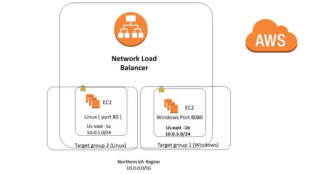
Pre-Step 1) we will have two EC2 instance; one we will have Windows 2008 server and another Linux Server
Step 1) In here we have two Websites ; one running on Linux Machine on Default port #80 and another one on Windows IIS Webserver on port 8080
Step 2) inside the IIS we need to go to IIS manager and change the binding to point to port 8080 and also create a custom rule so that the Windows Firewall will accept port 8080 as inbound
Step 3) When you install IIS webserver; you will have a folder called C:\inetpub\wwwroot
Then inside above folder ; make sure create a file and called it healthy.html and make sure you will be able to access via IE browser; that is http://x.x.x.x:8080/healthy.html
http://54.236.241.245:8080/healthy.html
Step 4) make sure on Linux machine you will have a file inside the folder
cd /var/www/html a filed called healthy.html ( otherwise your health check will not work) we will see it inside the lab.
So make sure when you type this in IE browsers http://54.174.68.136/healthy.html
you will see something ( use your own IP address)
Step 5) Now we will go over the labs ; the goal is that when we create a network ELB ; when you type in the URL:80 it goes to Linux Machine and when you type in URL:8080 it will go to Windows Machine.
Step 6) First we will configure the two Target Group (this is the best way to do it) then we will create Network ELB
Step 7) First I create a Target group called:
Step 8) for both group, when you do the health check, make sure pick HTML and in both cases use file healthy.html (remember we have created these file inside the Linux and Windows machine on corresponding folder)
Step 9) after you have created the target group ; you need to go to each Target group and click on the Target Tab ; then you need to pick correct EC2 and make sure you click add to register it and make sure save it. ( do not forget to save it).
Step 10) Now I will go create my Network ELB ; and in here make sure add two listeners in here , one for TCP port 80 and another one for TCP port 8080
Step 11) Make sure you will pick correct AZ and pick correct AZ in correct Public Subnet that you have , as you see in here we have choice of IP address ( we did not have this choice in Class ELB or Application ELB)
Step 12 ) We can also pick Elastic IP address. ( lets not do it now)
Step 13) Next we need to pick the Target group , so we can pick any of the target group for now I will pick WindowsTG1 ( it does not matter as we will see later on ).
Step 14) As you see when you pick the WindowsTG1 , it will fill in with the parameter we filled up before.
Step 15) Now if you go back to Target group on the left side and click on the description ; you will see in front of Load balancer , the Network ELB ; but when
you go to LinuxTG2 ; you do not see it ; since when I was doing step 12 in above ; I pick the WindowsTG1
Step 16) when you look at TAB called Target Tab on WindowsGP1 , you will see it says healthy ( which is good) but when you go under the Target tab of LinuxGP2, I see “Unused” since we did not pick on step 12
Step 17) Now let’s go to LoadBalancer on the Left side and when you click on the Listener ; it is Pointed to Windows; but we need to point windows only for port 8080 and Linux to point to port 80, so next to port 80 , click on it and the click edit; then pick Linux ,
Step 18) Make sure now port 80 goes to Linux
Port 8080 goes to Windows on the Listener Tab.
Step 19) Now if I go to left side and click on the Target group ; then when you click on the LinuxTG2 , you will see it is being initialized (first) then it will be healthy.
Step 20) If you go to ELB and click on the descriptions TAB and the copy and paste long DNS name you should be able to get the Linux machine with port 80 and Windows machine with port 8080
http://networkelb-f4556e12cdccebde.elb.us-east-1.amazonaws.com:8080/
Monitoring EC2 with Custom Metrics
You can monitor your EC2 using CloudWatch using:
Please note that RAM Utilization is a customer metric. By Default Ec2 monitors is for 5 mins interval, unless you enable detailed monitoring which will then make it 1 min intervals ( it will cost more)
Let’s go to google and search for Amazon EC2 Metrics and Dimensions
https://docs.aws.amazon.com/AmazonCloudWatch/latest/monitoring/ec2-metricscollected.html
we will do a lab and we will create a new EC2 and then we do customize Cloudwatch metric for Memory.
Step 1) We need to create a CloudWatch Role for EC2 so the EC2 can send some information to CloudWatch
Step 2) Go to IAM , and create a new Role called EC2CloudWatch
Step 3) Pick CoudWatchFullAccess as a Policy
Step 4) Now we will go and create an EC2 instance, then attached above Role to it ; then we will use some Perl Script so that we get customize Memory Utilization
Step 5) Before we do our lab, let’s go to google and type Monitoring Memory and Disk Metrics for EC2 Linux instance
https://docs.aws.amazon.com/AWSEC2/latest/UserGuide/mon-scripts.html
After we login into EC2 Linux, we will go to aparticular directory and run this Command
curl https://aws-cloudwatch.s3.amazonaws.com/downloads/CloudWatchMonitoringScripts-1.2.2.zip -O
Step 6) Now I will go to AWS and start new EC2 instance ( Linux)
Step 7) if you login into Linux, type these
sudo su
yum update –y
Step 8) Now we will install the Perl Script : ( install perl Syslogs and Protocols)
sudo yum install -y perl-Switch perl-DateTime perl-Sys-Syslog perl-LWP-Protocol-https perl-Digest-SHA.x86_64
Step 9) Now I will make a directory that we will install all of our stuff
Type:
mkdir /cloudwatchlab
cd /cloudwatchlab
Step 10) now we will paste the curl commands from Amazon Websites
curl https://aws-cloudwatch.s3.amazonaws.com/downloads/CloudWatchMonitoringScripts-1.2.2.zip -O
Step 11) Now we will unzip it
Step 12) If you type ls we will see it did create a directory called aws-scripts-mon
Now I will remove the Zip file that we downloaded
rm –rf CloudWatchMonitoringScripts-1.2.2.zip
Step 13) I go to the directory
cd aws-scripts-mon/
Then type ls and you see some perl script ( in green color)
mon-put-instance-data.pl
mon-get-instance-stats.pl
Step 14) Now before we push these script to Ec2 , lets go back to AWS console and look at Cloudwatch and we will see there is no Metric for Memory , but after we push above perl scripts ; we will see the Memory Utilization metrics
Step 15) Go to the Dashboards and create a new Dashboards and put CPU utilization ( as we see we do not Memory Utilization)
Call the Dashboard EC2custommetric (make sure save it)
As you click on EC2 and you will see these metric (as I mentioned in the beginning of Lab)
You can monitor your EC2 using CloudWatch using:
Step 16) Now we go back to our terminal windows and copy and paste this command from AWS websites
I will put this line of code to test and see if our EC2 instance can talk to CloudWatch
./mon-put-instance-data.pl –mem-util –verify –verbose
(Make sure run it at directory called aws-scripts-mon)
As we see we are ok Now.
Verification completed successfully. No actual metrics sent to CloudWatch.
Step 17) Now we will make sure we push the RAM utilization to cloud watch
Copy and paste
./mon-put-instance-data.pl –mem-used-incl-cache-buff –mem-util –mem-used –mem-avail
As we see it say successful
Successfully reported metrics to CloudWatch. Reference Id: 37ce5b72-48ae-11e8-800c-6be073b72519
Step 18) Now we do not want to do manually the above task we want to automated and we can use a concept called “crontab
Step 19) Go to directory etc
cd /etc
nano crontab
then go all the way down and type
*/5 * * * * root ./mon-put-instance-data.pl –mem-used-incl-cache-buff –mem-util –mem-used –mem-avail
Make sure in above remove the . and go to directory you had / cloudwatchlab/aws-scripts-mon
So correct line will be :
*/5 * * * * root /cloudwatchlab/aws-scripts-mon
/mon-put-instance-data.pl –mem-used-incl-cache-buff –mem-util –mem-used –mem-avail
Hint remember the directory is case sensitive
Exit and make sure save it.
Amazon AWS OpsWorks
What is OpsWorks ?
AWS OpsWorks is a configuration management service that provides managed instances of Chef . OpsWorks lets you use Chef to automate how servers are configured, deployed, and managed across your Amazon EC2 instances or on-premises compute environments.
It has these parts :
Chef : Chef turns infrastructure into codes , With Chef you can automate how you build ,deploy and manage your infrastructure
Stack – Stack is a group of resources such as EC2 instance, ELB , RDS instance
Layer – Layer exits within a stack and consist of things like Database layer, Application Layer
When you and I create for example an Application Layer (instead of creating manually) it will install Apache server and it will configure all the yum update and all other stuff for you.
We will see it in the Lab.
Now we will do a Lab now
Step 1) Go to Amazon Console and go to OpsWorks
Step 2) Go to region that you did not use it like Germany, as you see on EC2, there is no instance and we have only one default security group
Step 3) Create an Stack, here we will use the Chef 11 stack
Step 4) call it ASMWebPHPStack and leave all as default
Think of stack as production Stack; Test Stack, developer stack
Step 5) Now I will add a layer in here
Step 6) Pick Application PHP server =layer Type
Step 7) what above layer do; it will create an EC2 instance that will have Apache Webserver on it with all yum update on it
Step 8) now inside the Layer add an EC2 instance and called asmwebserver1, pick t2.micro and pick the AZ =eu-centeral-1a
Step 9) Start the instance, right now installing the instance and pre-configuring Apache Server and doing all the updates for us ( it will take some time) Remember if we go back to OpsWorks and these are Chef 11 stack ( pre define chef recipe)
Step 10) Lets back to Opsworks and click on Instance, and still booting
Step 11) go on the Left and get an (App) Application from Repository
An app represents code stored in a repository that you want to install on application server instances. When you deploy the app, OpsWorks downloads the code from the repository to the specified server instances.
Step 12) give the name ASMApp1
Step 13) put inside Git with this address , leave the rest as default value
https://github.com/aws-samples/opsworks-demo-php-simple-app
Step 14) Now click add App
Step 15) Now go back to instance on the left and see if it is complete
Step 16) If I click on the Ip address, you will see not fund; since the Apache Web server is running but we need go to App and deploy it
Step 17) It take about 2 mins to deploy , after it is finish when you go back to my instance and click the IP address I will see it is working and it shows at bottom got the name of instance
Simple PHP App
Congratulations!
Your PHP application is now running on the host “asmwebserver1” in your own dedicated environment in the AWS Cloud.
This host is running PHP version 5.3.29.
Step 18) Remember we do not need to SSH and just use the .php file.
Step 19) Now we will add another layer for ELB , but before we do add this layer ; we will go back to EC2 and left we will create an ELB and called it OpsWorkELB , but we do not add any instance to here .
Pick the security group called “
AWS-OpsWorks-PHP-App-Server”
and change to index.php and change the :
Interval =10 sec
Healthy threshold=3
Step 20) after it finished; when you go to Instance Tab , make sure you do not have any instance added here
Step 21) Now I go back to OpsWorks and try add the ELB layer to it
Step 22) you can add a new layer in another way ; go back to PHP app Sevrer ( layer) then you will see a Tab called network ; here we can add the ELB layer ; as we see this is another way of doing this .
Lets read the notes:
Note: After you attach an ELB to a layer, OpsWorks removes any currently registered instances and then manages the load balancer for you. If you subsequently use the ELB console or API to modify the configuration, the changes will not be permanent
Step 23) Now if you go back to layer ; you will See the ELB layer has been added but health is not good yet; it takes time ; now after a min ; it will be healthy and now if you click on long DNS name ; it will show the same Web page as before.
Step 24) Now if I go back to EC2 then on left click on ELB; on the instance TAB ; I will see the name of Instance (asmwebserver1) in here , remember we did not add anything in here before.
Step 25) If you go back to OpsWorks and click on the instance; you will see you have two other kinds
Step 26) Now I will go under instance inside Opsworks and add another instance and let’s called it
asmwebserver2
t2.micro
eu-centeral-1b
Step 27) now click on Start ; then we will see if I go to long DNS name (https://opsworkelb-1369249705.eu-central-1.elb.amazonaws.com/)
and keep refreshing ; I will see both the name :
asmwebserver1
asmwebserver2
Step 28 ) After about 2 mins , Now if I go back to EC2 and click on ELB , I will see the new instance has been added under the instance tab and it is in-service
Step 29) Now let’s go add another instance and called it :
asmwebserver3
t2.micro
eu-centeral-1c
Step 30) Now when I go to Long DNS name and keep refreshing ; I will see all three Webserver name
asmwebserver1
asmwebserver2
asmwebeserver3
Step 31) Now I will delate all the instance, layer and make sure remove ELB and delate all the Security group.
AWS provides various options to encrypt your data on S3.
There are 2 types of encryption:
Client side: Client encrypts locally using tool/software of their choices
Server Side encryption: Choose from available choices in AWS
In this video, our focus will be Server Side Encryption (SSE) since Client side is open to your preference/choices/requirement.
Server Side has 3 types of encryption as well:
SSE-S3: One click encryption
SSE-KMS: Using KMS
SSE-C: Not available in console. Customer provides the keys
Encrypt a file using SSE S3:
$ aws s3 cp abcd.txt s3://kms-test11 –sse
To create a kms key:
$ aws kms create-key -description “my kms key”
List all the keys:
$aws kms aws kms list-keys
This will not help us identify the correct key. Create an Alias for the key we created:
aws kms create-alias –alias-name alias/example-alias –target-key-id 1234abcd-12ab-34cd-56ef-1234567890ab
Then let’s list the alias of the keys as well.
$ aws kms list-aliases
To upload and encrypt a file to S3 bucket using your KMS key:
aws s3 cp file.txt s3://kms-test11 –sse aws:kms –sse-kms-key-id 4dabac80-8a9b-4ada-b3af-fc0faaaac5
Upload and encrypt a file using default KMS Key for S3 in the region:
aws s3 cp file.txt s3://kms-test11 –sse aws:kms
Want more information on how to become Amazon AWS Certified? Learn more!
2 Taft Court, Rockville, MD (map)


[bs_icon name=”glyphicon glyphicon-collapse-down”] It was a blessings night to serve about 35 people at women’s Shelter located in Rockville , MD. Please join us on 2nd Sunday of each month at 2 Taft court , Rockville MD .
Amazon AWS S3 Endpoint
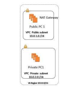
In Here we have One VPC =10.0.0.0/16 also we have three Subnet as follow
10.0.1.0/24 Public Subnet1
10.0.2.0/24 Private Subnet2
10.0.3.0/24 Public Subnet3
I have two server one is called Public1 inside the Public Subnet=10.0.1.0/24 with
Public Ip address: 34.201.13.154
Private Ip address = 10.0.1.183
Password -LphUKwynw9
I have another server in Private Subnet 2= 10.0.2.0/24
Private Ip address = 10.0.2.248
Password = rSB=zj6(EY
Step 1) I logon the PC called Public1 and rename it to Public1
Step 2) Since I can not access the Server located in Private subnet; first I need to RDP to Public1, then from that Server, I will do RDP to Private Server =
So I will RDP to Ip address =10.0.2.248
Step 3) Make sure from the server called Public1 I can ping 10.0.2.248, then try to RDP to PC called Private1=10.0.2.248 then rename the PC to Private1, so this way you will not get confused which one is which.
Step 4) In order to be able to use the AWS CLI command line, you need to make sure to install the AWS CLI commands on the server.
Step 5) here is the CLI command line for Windows
https://docs.aws.amazon.com/cli/latest/userguide/awscli-install-windows.html#install-msi-on-windows
Step 6) Since I want to show how you can connect to S3 from CLI; after installing the CLI; we need to make sure the Server has the IAM Role ( since we do not want to put the credentials inside the Instance
Step 7) Go to IAM and create a Role called S3Admin Role.
Step 8) Now go back to both EC2 instance ( Public and Private ) and make sure you assign the IAM roles to them.
Step 9) Now when I go to Public Server and I Type at command Prompt I type AWS S3 LS I will be able to see all y buckets:
C:\Users\Administrator>aws s3 ls
2018-01-28 21:21:01 asmtest4568
2018-01-28 21:20:31 test12345asm
2018-01-28 21:20:47 test698932asm
2018-01-08 17:51:16 testasm12345
Step 10)Now we come to our main Problem; that is goal is to make the Private PC that is located inside the Private Subnet be able to connect to S3 but via VPC S3 endpoint
Step 11) I want to make sure before we do above, we need to make sure the AWS CLI command line is installed on the PC=Private1 , so First I create a NAT gateway ( like what we did in the last Video) then I make sure pick Public Subnet ( 10.0.1.0/24) and then I configure the My Private RT is pointed to NAT gateway .
You will be able to ping 8.8.8.8 from Private1 after few mins.
Step 12) Now I go and Install the AWS CLI from the last link we had :
https://docs.aws.amazon.com/cli/latest/userguide/awscli-install-windows.html#install-msi-on-windows
Make sure in the same way you have given the Role to Public1, you would give to Private1 ( Role=S3admin) so that way you do not need the credentials.
C:\Users\Administrator>aws configure
AWS Access Key ID [None]:
AWS Secret Access Key [None]:
Default region name [None]: us-east-1
Default output format [None]: table
Step 12) after I finish installing AWS CLI on PC called Private1, I will remove the NAT gateway; so it will not have access to Internet then I will do Amazon VPC Endpoint S3
Step 13) Now I will remove NAT gateway from it.
Step 14) Now I will go on the Top go to VPC; then I will go to left side click on Endpoint, then click on create an Endpoint, now at the bottom middle pick the S3 and make sure in here pick Private Subnet
Hint: for Nat Gateway, make sure pick Public Subnet
For S3 Endpoint, make sure pick Private Subnet
Step 15) Here I will pick the Full access
Policy
Full Access – Allow access by any user or service within the VPC using credentials from any AWS accounts to any resources in this AWS service. All policies — IAM user policies, VPC endpoint policies, and AWS service-specific policies (e.g. Amazon S3 bucket policies, any S3 ACL policies) — must grant the necessary permissions for access to succeed.
Policy
Step 16) Now make sure the private Routing Table is pointed to this VPC-E as a routing table.
| 10.0.0.0/16 | local | Active | No |
| pl-63a5400a (com.amazonaws.us-east-1.s3) | vpce-d92aabb0 | Active | No |
Step 17) now and go and test it and it should work.


In this video, we share how we made a quiz skill that has a database integration so that your progress can be saved.
These are the components of an Alexa skill:
You will need 2 accounts to accomplish this:
import random # we need this package to shuffle the answers
questions= [“what’s the game’s author’s name?”, “what’s 2+2”, “what’s the capital of the United States?”,
“What’s the capital of China? “, “what’s the capital of India?”]
answers= [[“John”,”Jack”,”Jim”],[4,5,6],[“Washington DC”, “Seattle”, “New York”] ,[“Beijing”, “Shanghai”, “Tibet”],[“New Delhi”, “Mumbai”, “Banglore”]]
choiceLetter=[‘A’,’B’,’C’]
def quiz():
print( “Welcome to the game! You will get five questions. Type the choice letter(A, B, C) to enter the right answer”)
index=0 # keeping track of the index
score=0 # keeping track of the quiz score
for i in range(len(questions)):
print questions[index] # print question
answerIndex=0
shuffleAns= list(answers[index]) # copy the answer list to a different variable
random.shuffle(shuffleAns) #shuffle the answers
for answer in shuffleAns:
print (“({}) {}”.format(choiceLetter[answerIndex],answer))
if answer==answers[index][0]: # making sure that the correct asswer’s idndex after shuffling is saved
afterShuffle= choiceLetter[answerIndex]
answerIndex+=1
a= raw_input(“Enter your choice(A/B/C): “)
if a == afterShuffle:
print “Correct!”
score+=1
else:
print “wrong answer!”
index+=1
print “”
print (“\nYour score is {} out of {} \n”.format(score,len(questions)))
# This will run the quiz
quiz()
Want more information on how to become Amazon AWS Certified? Learn more!
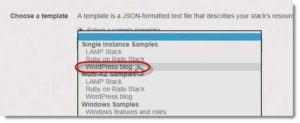
Step1: Go to Cloud formation Page Create a stack
Step 2: Click on select from templates and choose WordPress Blog
Step 3: Choose the parameters like username, password, key etc
** make sure you choose the right ssh key because we need to log in to the EC2 server later
Step 4: On the tag page tag the Stack resources with “Wordpress Blog”
Step 5: Click next and Create
Step 6: Navigate to output section and click on the URL. This will take you to your blog.
Step 7: Choose username and password and click next.
Step 8: You should have a blog setup now.
Step 9: SSH into your EC2 and paste the following command
$ sudo chown -R apache:apache path/to/wordpress
Step 10: Go back to WordPress and you may now install themes and customize your page.
Step 11: Select the stack that we created earlier and click on Actions. Then delete the stack. This will delete all the resources that were created by the stack.
Want more information on how to become Amazon AWS Certified? Learn more!
Autocomplete Lesson:
To add the autocomplete feature:
$ echo “complete -C aws_completer aws” >> ~/.bash_profile
$ source ~/.bash_profile
S3 CLI commands
Create a bucket:
$ aws s3 mb s3://test-saurav-123
Remove the bucket:
$ aws s3 rb test-saurav-123
Creating empty files in Linux :
$ touch file{1..10}
Copy a local file to a bucket:
$ aws s3 cp file1 s3://copy-file-saurav/
Copy Everything in local file to a bucket:
$ aws s3 sync . s3://copy-file-saurav/
$ crontab -e
Create a script to save all files to S3 bucket every (x) minutes/hours/days or months
• $ vim sync.sh
• press i for insert
• #!/bin/bash
• $ aws s3 sync /home/ec2-user/Documents/ s3://copy-file-saurav
• Press Esc
• Type :wq! To save and exit
• $ Chmod 500 sync.sh
The above command will make it executable
On command line type this to create a cron job:
$ crontab –e
• press I to insert
• paste: */1 * * * * /home/ec2-user/sync.sh
• The above line will sync files every minute. For every day use:
* */1 * * * /home/ec2-user/sync.sh
• save with :wq!
To exclude a file with certain extension:
$ aws s3 sync /home/ec2-user/Documents/ s3://copy-file-saurav –exclude ‘*.rtf’ –acl
public-read –storage-class STANDARD_IA
To exclude a file with public read permission and put in in s3- IA storage class:
$ aws s3 sync /home/ec2-user/Documents/ s3://copy-file-saurav –acl public-read —
storage-class STANDARD_IA
For further reference visit:
https://docs.aws.amazon.com/cli/latest/reference/s3/index.html
Want more information on how to become Amazon AWS Certified? Learn more!
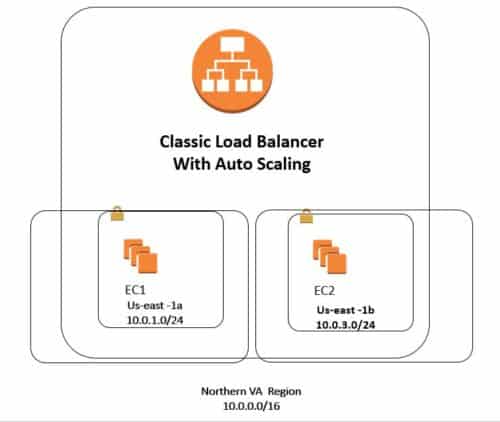
Step 1) I will take image of One of My Web server called Webserver1, when I go to public IP address I will see the
content of the Web server
Step 2) I will stop the Instance; then Take an image of it. Call it “Webserver1Image”
Step 3) Now I will see the New Image under the Image on the left ( Under AMI)
Step 4) I will go and create an Elastic Load Balance; and I will call it AutoscaleELB, then choose a Sec Group
and then I will pick two Subnets on different AZ ( in here it will be us-east-1a and us-east-1b
Step 5 ) I Will not add any instance under this ELB, but I will add it later on with Autoscaling
Step 6) Now I will see my AMI is already online
Step 7) now I go and start My Auto scaling Process, on the left, I click on launch configuration
Step 8) click to create an “Auto Scaling Group”
Step 9) First you need to define a template that your Auto Scaling group will use to launch instances.
Step 10) Click on “Create Launch configuration “
Step 11) Here you will pick “From my AMI “ from left it is called “Webservwer1Image “ which we did on step2
Step 12 ) After selecting the AMI, called it “AutoscalingLunchconfiguration”
Step 13) Click Advanced configuration and for the IP address pick :
Assign a public IP address to every instance.
Step 14) For Security group pick something with HTTP access
Step 15) Use one of your Keys and start it up
Step 16) now it will take you to Auto scaling group, lets called it “Auto Scaling group 1 “
Step 17) here make sure pick correct VPC and then “Start with two instances” add the AZ from subnet drop down and
pick Correct Subnet us-east-1a and us-east-1b, ( Must Match with ELB that I created before )
Step 17 b) Make sure click Advanced and in here picking ELB ( that you created in Step 4, that was called: “AutoscaleELB”
Step 18 )Now I will configure scaling Policy :
( in here you will tell if the CPU is above 80% for
example add one instance, and If the CPU is below 30% you will remove one of the instances.
Scale between Min 2 and Max 5
Step 19 ) Scale between 2 and 5, that is if My CPU utilization goes above 80 %, the maximum EC2 instance I can have
will be 5 and Min will be 2
Step 20) Now I will add some Policy that is if CPU goes above 80% add “1” instance, and if the CPU drops below
30 % I will remove one EC2 instance. Remember the Min EC2 instance will be 2 and Max EC2 instance will
be 5
Step 21 ) now you can create a notification, then put your e-mail address for
Step 22 ) As it is finalizing the process when I go to EC2 I will see two instances will come up, let us call them as follow
Autoscaling1 created 9-17-2017
Autoscaling2 created 9-17-2017
Step 23 ) Now if I go to ELB, I will see it last two instances that were created from Auto scaling and Also I will see the Long
DNS name, when I copy and paste DNS, I will see the same content of Web server 1 that was tested in Step 1
Step 24 ) Now I will do a test since I can not create an 80% CPU utilization; what I can do I will make sure one of the EC2
instance dies ( so I terminate) and see if Auto scaling group create a new EC2, so I will select EC2 from us-east-1a
and terminate it.
Step 25 ) Now after killing the EC2 in us-east-1a I will see that under the Load balancer it has only one in service
which is US-east-1b and when I go back to EC2, I will see the auto scaling will provisioning a new EC2 in
us-east-1a and when I go back to the Elastic Load balancer, I will see now two EC2, one from us-east-1a and
another one from us-east-1b. Also, go to Auto scaling group and check the activity Tab, you will see one
terminating and then another one is initializing.
Step 26) Now When I go to Auto scaling group on the left and click on the History Tab; I will see the history what
is happening.
Step 27 ) let us go to EC2 and give the new EC2 name as follow :
Autoscaling 3 created 9-17-2017
Step 28 ) now we see this {Autoscaling 3 created 9-17-2017 } has been shown under the Elastic Load Balancer
Want more information on how to become Amazon AWS Certified? Learn more!

Lambda is an event-driven compute service. We have functions that execute when a trigger is triggered. In today’s lab, we will set up a trigger with Cloud watch Events.
On top of that, we will need an IAM role that gives our lambda function permissions to Stop EC2 Instances. We will also add Cloud watch permissions in that role so that the lambda function can log the event every time it is triggered.
Let’s get started with setting up the role:
You should see a list of policies. Search for AmazonEC2FullAccess and check the box.
Now we should have a role that we can attach to our Lambda function.
Now Let’s work on our Lambda function:
import boto3
client=boto3.client(‘ec2’)
def lambda_handler(event, context):
response=client.describe_instances()
for reservation in response[“Reservations”]:
for instance in reservation[“Instances”]:
print(instance[“InstanceId”] + “stopping”)
id=[instance[“InstanceId”]]
client.stop_instances(InstanceIds=id)
return(“Completed”)
Cloudwatch Events Setup:
Now let’s go to our EC2 console and launch or start few ( 3 ) instances.
It’s time to test the Lambda Function. Since we can’t wait until 12 am, let’s test the event manually.
Go back to the Lambda function we created earlier and click Test.
Check your EC2 console. Your EC2 instance must be stopping.
That concludes the lab.
Terminate the EC2 instance that you created earlier.
*If you have errors in lambda function we can go to cloud watch logs and troubleshoot.
Want more information on how to become Amazon AWS Certified? Learn more!
Amazon AWS EFS with ELB
EFS (Elastic File System) Features
Now will do a Lab,
In here we will have two EC2 instances (One on each Subnet and different AZ), then we will create an EFS and Mount on this EC2, I will boot up and Amazon AMI and then install the Apache Web server, and on one of the EC2 we will create the index, html and we will see it will be on 2nd EC2 and then we will test it via Elastic ELB and we will see our sample web page.
Step 1) I go to AWS and click a new EFS
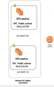
Step 2) I choose the VPC=10.0.0.0/16 then I will choose two Subnet 2 and Subnet 3 in each different AZ
us-east-1a with Subnet 1= 10.0.1.0 /24
us-east-1c with subnet 3= 10.0.3.0/24
Make sure pick correct Security Group ( Here I pick RDP, HTTP, ICMP) and default security group,
Click Next
Step 3) Give the Name =EFSWebsites, leave the default and click next
Step 4) now it should be creating the EFS ( when it is finished it will show Available)
Step 5) Now I will go to EC2 and create two EC2 with Amazon AWS and call it EFS-east1a and EFSeast1c
Put the first EC2 ( called EFS-east1a inside the Subnet 1)
Put the 2nd EC2 ( called EFS-east1c inside the Subnet 3)
Step 6) make sure use same security group as above.
Step 7) Now I will SSH to the first instance ( EFS-east1a) and here we will use the keygen to create a .ppk ( since my key was in format of .pem
Step 8) in order Yum with two windows, please make sure pay attention to private IP address 10.0.1.x ( 1st instance) and 10.0.3.x (2nd instance)
Step 9) type these
sudo su ( to put in root position)
yum update -y
yum install httpd –y ( to install the Apache server)
Service httpd start ( to start the Web server service)
Step 10) now above will create a directory for us at /var/www/html
So let’s go to that directory
[root@ip-10-0-1-8 ec2-user]# cd /var/www/html
[root@ip-10-0-1-8 html]# ls
As we see when I type ls there is nothing inside my directory now.
Step 11) now go to the 2nd instance (10.0.3.x) and ssh to it and type same commands as before
make sure go back to root on both instance:
Step 12) Now I will go and create a classic ELB (call it EFSELB) and include these two instances and make sure pick correct Security group as for those instances. ( pick also default Sec group)
Step 13) change the interval to 6 sec and also the Healthy threshold to 2 retry.
Step 14) If I go to instance tab; I will see the status out of service ( since we have no index.html )
Step 15) Now I go back to EFS and follow the instruction on what to do: in here click on :
Amazon EC2 mount instructions
I do not need to do these steps since my Linux AMI already has it :
————————————————–Skip these steps—————————————-
Install the nfs client on your EC2 instance.
——————————————————————————————————
Now if you get this message in the box :
Your Amazon VPC is not currently configured to enable mounting using DNS names. To enable this feature go to the Amazon VPC console; in the Actions menu, select “Edit DNS Resolution” and “Edit DNS Hostnames” and make sure both are set to “Yes”. For instructions on mounting your file system using a mount target IP address instead of a DNS name, please see our technical documentation.
Now after you did the DNS now you can copy and paste this commands to Mount your file system
sudo mount -t nfs4 -o nfsvers=4.1,rsize=1048576,wsize=1048576,hard,timeo=600,retrans=2 fs-a9ffaee0.efs.us-east-1.amazonaws.com:/ efs
But now instead of /efs directory we will mount it at /var/www/html (at the both of instance only)
sudo mount -t nfs4 -o nfsvers=4.1,rsize=1048576,wsize=1048576,hard,timeo=600,retrans=2 fs-a9ffaee0.efs.us-east-1.amazonaws.com:/ /var/www/html
Step 16) if you paste above commands and does not work and it takes time; you need to go back to your both instance and make sure you have added the default security group ( also inside the EFS)
Step 17) now I will go to one of the instance ( for exam first instance) then I go to directory
Cd /var/www/html
And type nano index.html
And write something inside of it, then we will see this file inside 2nd instance
Step 18) Now when I go to next instance, I will see the index.html with same content
Step 19) So I have mounted this EFS file on directory /vasr/www/html
Step 20) Now if I go to my ELB, and I copy and paste long DNS name :
EFSELB-30545612.us-east-1.elb.amazonaws.com
I will see the content of index.html
Step 21) Now I can go to ROUTE 53 and create an “A” record with Alias and point to ELB, then try to open with my domain name
Hamedtest100.com
So as we see in here, it looks like
Here are the difference between EBS, EFS, and S3
Amazon EFS is a file storage service for use with Amazon EC2. Amazon EFS provides a file system interface, file system access semantics (such as strong consistency and file locking), and concurrently-accessible storage for up to thousands of Amazon EC2 instances.
Amazon EBS is a block-level storage service for use with Amazon EC2. Amazon EBS can deliver performance for workloads that require the lowest-latency access to data from a single EC2 instance.
Amazon S3 is an object storage service. Amazon S3 makes data available through an Internet API that can be accessed anywhere.
Want more information on how to become Amazon AWS Certified? Learn more!
EBS Vs Instance Store, Snapshot, and Volume
Amazon (EC2) Elastic Compute Cloud
Volumes Vs Snapshots
Volumes Vs Snapshots – Security
Snapshots of Root Device Volumes
Now we will do a Lab
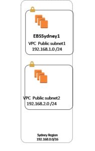
Step 1) I go to Sydney Section; in here I have a VPC =192.168.0.0 /16 and then we have two public Subnet 1, 2
192.168.1.0/24
192.168.2.0/24
Step 2) I will go to EC2 and pick one Windows 2008 server with EBS, and then I will see also under the Volume section on the left side it has the new Volume.
Step 3) Then after I log in, I will go to Windows 2008 server and rename it , then I will install IIS Web server , then I go to c:\intepub\wwwroot and create an index.html file and save it in this folder ( hint: make sure the extension is a .html file not .txt, make sure use folder option to find out if the extension is turn off )
Step 4) Now go and make sure you type IP address of the Public in IE or Google Chrome, you should be able to see the content of the homepage
Step 5) Now I will go stop and take Snapshot of this EC2, as we see when I select the EC2 called EBSSydney1, in here I can extend the volume size, let’s give the name Image of EBSSydeny1.
When you create an EBS image, an EBS snapshot will also be created for each of the above volumes.
Step 6) Now I will see “Image of EBSSydeny1” under AMI and also under the snapshot on the left side
Step 7) So what does it mean, I can have this as a baseline and start from this AMI, I can get another EC2 instance with an exact same software package ( Like IIS and web server).
Step 8) Now I will go and Start a new Launch of EC2, but in here I will use My AMI
Step 9) go thru same process as before and pick this New EC2 inside the public subnet 192.168.1.0/24 and give name EBSSydney2
Step 10) As we see as we go thru these steps ( I can uncheck Delete on termination, but I cannot do this when I do instance store )
Step 11) As we see now under the EC2 I will see two instances and also under the volume I will see two Volume
Step 12) Now I will connect to new EC2 called EBSSydney2 and RDP to it and also if I copy and paste the public address I should see the same content of EBSSydney1
Step 13) after login and put the password I will go and see I have IIS installed on folder c:\inetpub\wwwroot\index.html, then I will rename the Computer name to EBSSydeny2
Step 14) Now If I want I can increase the Volume size of EBSSydney1 from 30 GB to 35 GB, all I have to do go to Volume and click on action and then modify it.
Step 15) I will go and restart the EBSSydney1 and to see if I got for extra 5 GB Storage, as we see when I go to volume and I click on EBSydney1 and look under the Status tab; I will see some % that is trying to optimize it.
Step 17) Make sure State in-use – completed (100%)
Step 18) if you go to Server Manager at taskbar; then click on the storage; now I will see extra space of 5.00 GB and now all you have to do highlight it and then you can extend your C drive.
Step 19) now I can see C drive is 35GB
Step 20) Now let’s say I want to attach a new Volume to EBSydney1 as D Drive=50 GB; So I can go to Volume on the left and then create a new Volume ( here I can encrypt it) and then attached to EBSydney1
Here is the ID of new Volume: vol-0401eb87ba30edb96; ( for Example)
Step 21) Lets rename is called it “New Volume Made “Now on right side Column I will see it says available (instead of in use)
Step 22) let’s go an attached to EBSsydney1 (the size of volume is 50G)
Step 23) Now If I go to EC2 and click on EBSydney 1 and at the bottom, I will see both root and this extra attached Volume to it
Step 24) Now go to Ebsydney ( via RDP) and go to server manager and click on storge I will see this new 50 GB drive ( extra HD) and then I can right-click on it, initialed it and then right click and create a volume and use all 50 GB space and then give the Drive letter “D”
Step 25) Now I will have two Hard drive C and D drive. Let’s imagine my D drive is used for DATA, so I will go and store a file called Data.txt inside it.
Step 26) so Up to now I have two EC2
EBSsydney2 with C drive
EBSydney1 with C and D Drive
Step 27) Now since all of these EBS are attached to EC1 via network; I can detach the Volume D Drive from EBSsydney1 and connect to EBSsydney2
Step 28) After I do above and Detached, then I will see status as “Available”
Step 29) Now I will go and Attached this Volume ( D Drive) to EBSsydney2
Step 30) Now when I go EBSsydney1, I will see D drive is not there; but when I go to EBSsydney2, I will see it has D drive and also I will see my data is still there.
Step 31) So we see the EBS Volume can be attached to only one EC2 at a time, and now when I created the New Volume and if it was Encrypted the attached volume will be also encrypted.
Step 32) Now I will go and create Instance (instead of EBS) and we will see that I cannot stop it, but only Restart or Terminate
Step 33) Go to EC2 and Create a new EC2, then on the left side click on Community AMI; then make sure select Root type As “ Instance Store “
Step 34) go thru the process and pick first AMI, as you see there is no Free Tier and pick M3.meduim and then put public subnet
Step 35 ) On the add storage type; read it :
Your instance will be launched with the following storage device settings. You can attach additional instance store volumes to your instance. You can also attach additional EBS volumes after launching an instance, but not instance store volumes. Learn more about storage options in Amazon EC2.
Step 36) click Add new volume and as you see you do not have any good option and also you cannot click on “Delete on Termination “ and also you cannot encrypt. Give the name
InstanceSydney1
Step 37) As you see it is not FREE; so as soon as we did it we will delete it.
Step 38) As you see when you created an Instance Store; you do not have any Volume ( like when we created the EBS stuff)
Step 39) now when you click action and look at the state I can only reboot or Terminate; so I cannot stop it, I cannot take the image of it.
Part 1
Part2
Want more information on how to become Amazon AWS Certified? Learn more!
Simple Notification Service (SNS)
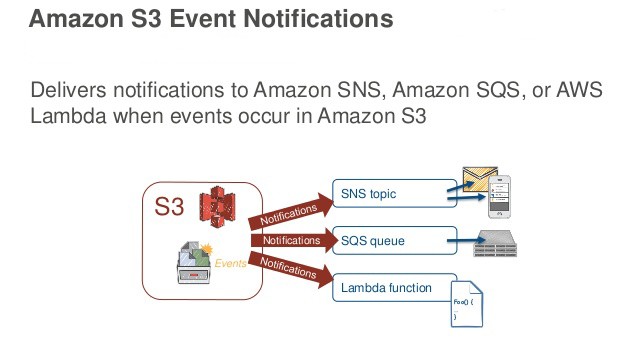
SNS is integrated into many AWS services. We are able to use it to receive notifications when events occur in our AWS Environment. With CloudWatch and SNS a full environment monitoring solution could be created that notifies administrators of alerts, capacity issues, downtime, changes in the environment, and more!
Step 1) We will create a TOPIC. Call it “A picture was uploaded to S3 buckets”
Step 2) lets create a Subscription, in here we will use protocols “e-mail”
The choice of Protocols are:
Step 3) Then insert your e-mail in here :
Step 4) Now As we see it is pending, so go to above e-mail and then accept subscription; then you need to confirm subscription
Step 5) Now when I go back to AWS SNS, I will see new Subscription ID
Step 6) Now if you need to add another Subscription; you can click Subscription; then chose Mobile phone ( to get txt) and provide your cell phone number.
Step 7) Now I will test it by sending a Publish to this topic; Via Myself, remember I can use the notification also when I trigger some events.
Step 8) Now that all is OK, I will go to S3 and create a Buckets and have a trigger a SNS3 to e-mail when I get a file uploaded to the S3
Step 9) Go to S3 and create this Buckets “testswithsns” with all default value
Step 10) Then go to properties of that buckets and click on the events
Step 11) Pick the event = “Object create”, As you see when you want select it: you have choices SNS topic, SQS Queue or Lambda Function
Step 12) I pick SNS and pick the topic I did on the first steps called “whenAfileisuplaodedtoS3 “
Step 13) Now when I upload pictures to my S3 buckets I will see notifications.
Want more information on how to become Amazon AWS Certified? Learn more!
![]()
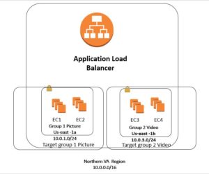
Step 1) Create Target Group 1 (Pic) and Target Group 2 (video)
Step 2) Associate /Register the above group with EC1(Pic1) and EC2 (Pic2) with group 1
click target Tab ( Make sure click to add to register , then Save )
Step 3) Associate /Register the above group with EC3(video3 ) and EC4 (Video 4) with group 4
click target Tab ( Make sure click to add to register , then Save )
Step 4 ) Now we will click on the Application Load Balancer and go thru steps
Step 5) After selecting the Security Group ( port 80) then we will pick both target group 1 and target group2
if we did not create target group 1 and target group 2 we had to do it here. This way is easier to
understand the material.
Step 6) Here I pick Picture as a default group ( it does not matter which one we pick) we will see later on; as
we see rest of parameter is filled up .
Step 7) We wait about 5 mins so the state goes from Provisioning to Active . Now if you go to target groups
you will see both of the instance at group 1 (pic) are healthy . But when you look at Group 2(video)
you will see as unused , since we have to link the video to Application Load Balancer.
Step 8) Now If I copy and paste long DNS name https://applicationloadbalancer-780517374.us-east-1.elb.amazonaws.com/
It will show page that correspond to Pic1 and Pic2
Step 9) Now if you go back to target group and click on Target group 1( pic) on the first tab, I see the Load balancer is
shown in here ; but when I click on the target group 2( Video) on first tab I do not see the Load balancer associate
here. So I need to go to Load Balancer and change the Rule ( last tab) .
Step 10) In here we see the default rule is pointed to Group1 (pic) .
Step 11 ) click on View/Edit Rule
Step 12) Now we will add content rule and I will use for path *Picture* go to picture group
Now we will add a content rule and I will use for path *Video* go to Video group
Step 13) Now if I paste that long DNS name with /picture.html it will shows the content from EC1 and EC2 ( after refresh)
https://applicationloadbalancer-780517374.us-east-1.elb.amazonaws.com/picture.html
Step 14) Now if I paste that long DNS name with /video.html it will shows the content from EC3 and EC4 ( after refresh14)
https://applicationloadbalancer-780517374.us-east-1.elb.amazonaws.com/video.html
step 15) now if you go back to target Group 2 (video) then on fist tab we will see it is now associated with Load Balancer
Want more information on how to become Amazon AWS Certified? Learn more!
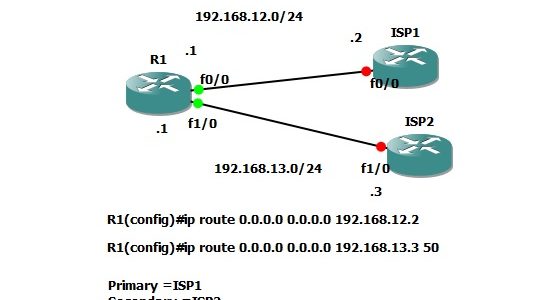
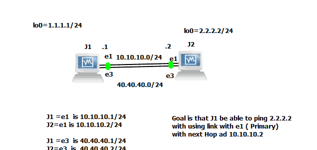
Cisco IP SLA (Service Level Agreement) is very similar to concept of Frame-relay – Like Committed information rate. That is your Service Provider ISP, will tell you that you are guaranteed to get particular BW from them , with Min value of something ; but can go to higher value. Same Concept apply to Ip SLA
Read more »

Now I will do small Lab:
In This Lab I have 6 host connected to a Switch, with Ip address
as follow 200.1.1.x where x=Router number,
I will go to my multi-layer switch and configure VACL=VLAN Access-list
Read more »
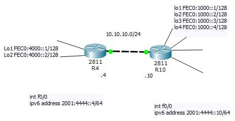
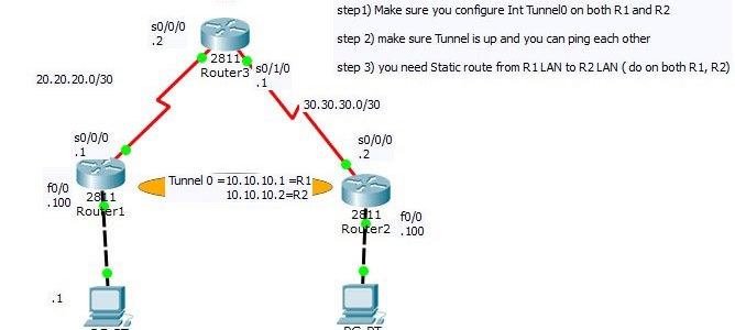
Now I will do small Lab: The Goal is that seated at R4 be able to ping all the loopback of R10 , in order to do this , we will cover Static Route.
R4=10.10.10.4
R10=10.10.10.10 connected via LAN link
Also I will have IPV6 as follow:
r4 f0/0=2001:4444::4/64
r10 f0/0=2001:4444::10/64
Read more »

Here what I have:
Pc1=10.10.10.1
pc2=10.10.10.2
pc3=10.10.10.3 connected to port f0/3 which is located in Lobby
hacker=10.10.10.4
The goal is I want to protect the port f0/3 located in lobby and make sure only PC3=sales3 be able to connect and do his work.
Hint:You will go int f0/3 and start with switchport?
Read more »
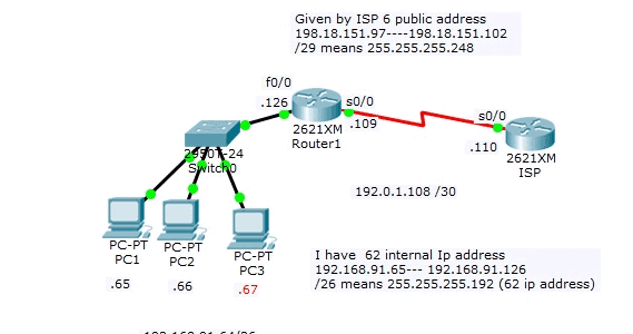
NAT = Network address translation
Remember the private IP address
10.0.0.0 — 10.255.255.255
172.16.0.0 —-172.31.255.255
192.168.0.0.—– 192.168.255.255
The goal is to convert your Private IP address to PUBLIC address so that your internal people can access the internet
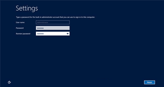
Login to your Windows server 2012 as an Administrator. When your log in is completed the Server Manager will be opened automatically, if it doesn’t open then you must open it manually. Read more »
Another advantage of having a client-server model is centralizing storage. Instead of having data dispersed among multiple hard drives on different client machines, we can store the all mission critical data on a central hard drive on the server. Read more »
Another advantage of having a client-server model is centralizing storage. Instead of having data dispersed among multiple hard drives on different client machines, we can store the all mission critical data on a central hard drive on the server. Read more »
Another great feature of Server 2012, is how the Delegation of Control Wizard simplifies adding rights for common tasks to groups or administrators. Read more »
At this stage, we have an Active Directory with some groups and member users defined; however, now we need to add member computers to the domain. In the next step, we join the domain from our client computer and login with one of the users we have created. Read more »
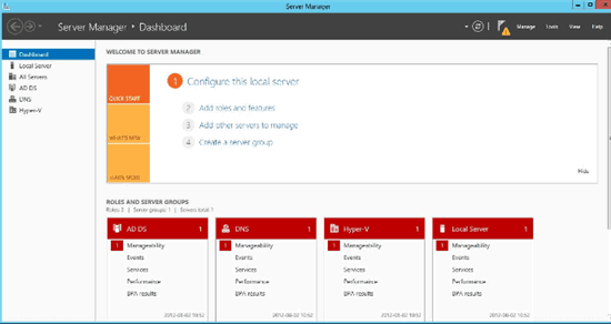
Open Server Manager.
Select AD DS to verify post installation. Read more »
For centralized management of the users, resources, and group policies we need to promote the Window Server machine from a member server to an Active Directory (AD) Domain Controller (DC). Read more »
Microsoft publishes hardware minimum requirements for the software it sells. For Windows Server 2012, the minimum requirements are:
Processor: Minimum: 1.4 GHz 64-bit processor
Ram: Minimum: 512 MB
Disk Space: Minimum: 32 GB
Other requirements:
DVD drive
Super VGA (800 x 600) or higher-resolution monitor
Keyboard and Microsoft® mouse (or other compatible pointing device)
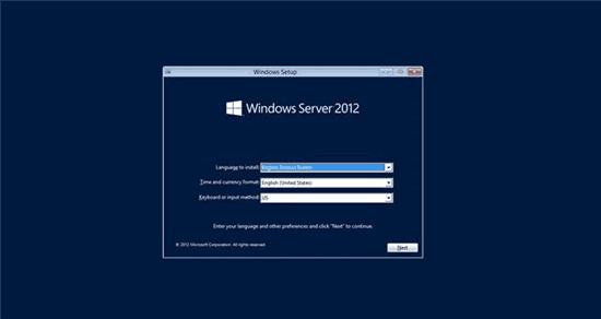
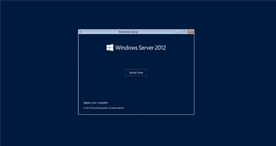
Internet access
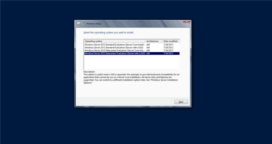
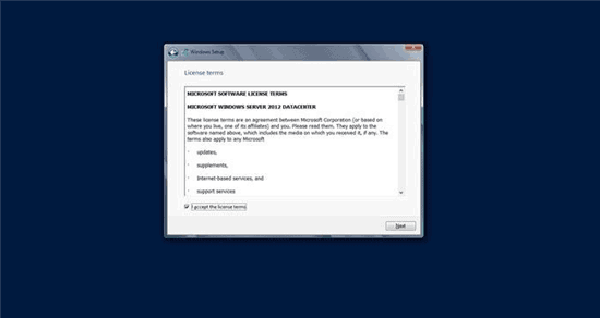
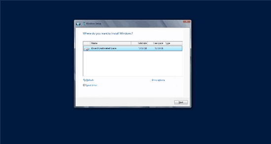
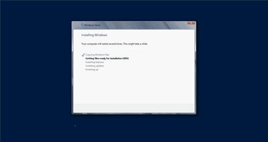
Insert the server 2012 DVD in the server and to through the following steps:


To Become Microsoft Certified please Check out the Link;
In this step, you’ll use the Amazon VPC wizard in the Amazon VPC console to create a VPC. The wizard performs the following steps for you: Read more »
Taking a Network+ exam? Follow us on Facebook and ask us about our study group.
The (Open Systems Interconnection) OSI has been developed by International Organization for Standardization (ISO). The OSI model provides a framework for creating and implementing networking standards and devices and describes how network applications on different computers can communicate through the network media. In this post, each of the seven layers of the OSI model will be explained in simple terms.
Layer 1 – Physical layer
Physical layer defines the physical medium itself. It details how cables, connectors and network interface cards are supposed to work and how to send and receive bits. When a networking problem occurs, many networking pros go right to the physical layer to check that all of the cables are properly connected and that the power plug hasn’t been pulled from the router, switch or computer, for example.
Layer 2 – Data Link
Data Link layer defines the format of data on the network. The data link layer is divided into two sub layers: The Media Access Control (MAC) layer and the Logical Link Control (LLC) layer. MAC layer is used for hardware addressing and for controlling the access method. The LLC layer is used for used for flow control and error detection.
Layer 3 – Network
Network Layer defines device addressing, routing, and path determination. Network layer acts as a boundary between the host and the subnet. It deals with routing issues, deadlock and conjestion issues caused by increased number of packet data transfer and decreasing the performance etc.
NFS uses Internetwork Protocol (IP) as its network layer interface. IP is responsible for routing, directing datagrams from one network to another. Even though IP packets are addressed using IP addresses, hardware addresses must be used to actually transport data from one host to another. The Address Resolution Protocol (ARP) is used to map the IP address to the hardware address.
Layer 4 – Transport
Transport layer is responsible for getting the entire message across, establishes and terminates connections between two computers and keeping track of fragmentation and out-of-order packets. Used for flow control and data recovery.
Two transport protocols, Transmission Control Protocol (TCP) and User Datagram Protocol (UDP), sits at the transport layer.
TCP establishes connections between two hosts on the network through ‘sockets’ which are determined by the IP address and port number.
UDP on the other hand provides a low overhead transmission service, but with less error checking.
Layer 5 – Session
This layer defines how to establish, manage and terminate connections between applications.
Layer 6 – Presentation
The Presentation layer defines the data formats. The compression and encryption are also defined at this layer.
Layer 7 – Application
This layer provides network services to the end-users. In general: Layer 7 is the layer that users interact with directly, for example, users browse applications like web browsers (Google Chrome, Firefox, Safari, etc.), Email Applications (Outlook, Thunderbird, etc.), Chat Applications ( WhatsApp, Skype, Viber, etc.) directly are the examples of layer 7 applications.
References: Network World
Want more information on how to become CompTIA Network+ Certified? Learn more!
Taking a Network+ exam? Follow us on Facebook and ask us about our study group.
WiFi is not an acronym but a brand name created by a marketing firm that’s meant to serve as an interoperability seal for marketing efforts. WiFi technology however provides wireless Internet access via the use of radio waves which transmit a signal to a wireless enabled device. You can access this type of connection from up to one hundred feet away and the performance of the connection can vary according to the 802.11 standard being used and the number of devices connecting to the router simultaneously. The standard known as the 802.11 offers a number of different levels of bandwidth usage symbolized by a letter.
The IEEE naming scheme for the standard is a little tough to get used to, and in an effort to make it easier to understand, the Wi-Fi Alliance has come up with some simpler names.
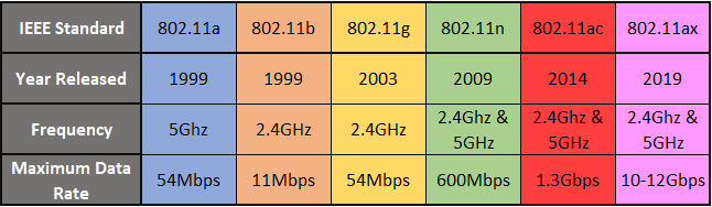
802.11a
The first “letter” following the June 1997 approval of the 802.11 standard, this one provided for operation in the 5GHz frequency which makes it less prone to interference and with data rates up to 54Mbps. It introduced a more complex technique, known as OFDM (orthogonal frequency division multiplexing) for generating the wireless signal.
802.11b
Released in September 1999, it’s most likely that your first home router was 802.11b, which operates in the 2.4GHz frequency and provides a data rate up to 11 Mbps and has a range up to 150 feet. 802.11b components are cheap, but the standard has the slowest maximum speed of all the 802.11 standards.
802.11g
Approved in June 2003, 802.11g was the successor to 802.11b, able to achieve up to 54Mbps rates in the 2.4GHz band, matching 802.11a speed but within the lower frequency range. 802.11g standard uses the same OFDM technology introduced with 802.11a. 802.11g is backward compatible with 802.11b devices: an 802.11b device can connect to an 802.11g access point (but at 802.11b speeds).
802.11n (Wi-Fi 4)
The first standard to specify MIMO (Multiple Input Multiple Output), 802.11n was approved in October 2009 and allows for usage in two frequencies – 2.4GHz and 5GHz, with speeds up to 600Mbps. When you hear wireless LAN vendors use the term “dual-band”, it refers to being able to deliver data across these two frequencies.
802.11ac (Wi-Fi 5)
Current home wireless routers are likely 802.1ac-compliant, and operate in the 5 GHz frequency space. With Multiple Input, Multiple Output (MIMO) – multiple antennas on sending and receiving devices to reduce error and boost speed – this standard supports speeds ranging from 433 Mbps all the way up to 3.46Gbps. Some router vendors include technologies that support the 2.4GHz frequency via 802.11n, providing support for older client devices that may have 802.11b/g/n radios, but also providing additional bandwidth for improved data rates.
Pending Wi-Fi standards
802.11aj
Also known as China Millimeter Wave, this defines modifications to the 802.11ad physical layer and MAC layer to enable operation in the China 59-64GHz frequency band. The goal is to maintain backward compatibility with 802.11ad (60GHz) when it operates in that 59-64GHz range and to operate in the China 45GHz band, while maintaining the 802.11 user experience. Final approval was expected in November 2017.
802.11ak
There are some products in the home-entertainment and industrial-control spaces that have 802.11 wireless capability and 802.3 Ethernet function. The goal of this standard is to help 802.11 media provide internal connections as transit links within 802.1q bridged networks, especially in the areas of data rates, standardized security and quality-of-service improvements. It reached draft status in November 2017.
802.11ax (Wi-Fi 6)
Known as High Efficiency WLAN, 802.11ax aims to improve the performance in WLAN deployments in dense scenarios, such as sports stadiums and airports, while still operating in the 2.4GHz and 5GHz spectrum. The group is targeting at least a 4X improvement in throughput compared to 802.11n and 802.11ac., through moreefficient spectrum utilization. Approval is estimated to be in July 2019.
802.11ay
Also known as Next Generation 60GHz, the goal of this standard is to support a maximum throughput of at least 20Gbps within the 60GHz frequency (802.11ad currently achieves up to 7Gbps), as well as increase the range and reliability. The standard is expected to be approved between September and November 2019.
802.11az
Called Next Generation Positioning (NGP), a study group was formed in January 2015 to address the needs of a “Station to identify its absolute and relative position to another station or stations it’s either associated or unassociated with.” The goals of the group would be to define modifications to the MAC and PHY layers that enable “determination of absolute and relative position with better accuracy with respect to the Fine Timing Measurement (MTM) protocol executing on the same PHY-type, while reducing existing wireless medium use and power consumption, and is scalable to dense deployments.” The current estimate on approval of this standard is March 2021.
802.11ba
Otherwise known as “Wake-Up Radio” (WUR), this isn’t a crazy morning zoo-crew thing, but rather a new technology aimed at extending the battery life of devices and sensors within an Internet of Things network. The goal of the WUR is to “greatly reduce the need for frequent recharging and replacement of batteries while still maintaining optimum device performance.” This is currently expected to be approved in July 2020.
References
actiontec. (n.d.). The evolution of WiFi standards: a look at 802.11a/b/g/n/ac. Retrieved from actiontec.com: https://www.actiontec.com/wifihelp/evolution-wi-fi-standards-look-802-11abgnac/
Cisco. (n.d.). What Is Wi-Fi? Retrieved from www.cisco.com: https://www.cisco.com/c/en/us/products/wireless/what-is-wifi.html
Phillips, G. (n.d.). What Are Wi-Fi Standards? Retrieved from www.makeuseof.com: https://www.makeuseof.com/tag/understanding-common-wifi-standards-technology-explained/
Want more information on how to become CompTIA Network+ Certified? Learn more!
