Inter VLAN Communication (Router on Stick)
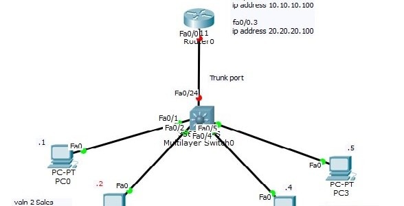
Earlier we built and tested the following topology:
Now that we have a better understanding of how routers work, we will solve the problem of inter VLAN communication with a different solution. The problem with the previous solution is scalability. For every VLAN we need to dedicate a link to carry traffic to the router. The routers by default have only two interfaces. How to support more than two VLANs? We will be using additional ports on the switch as well, which will leave less for the end clients.
A trunk can carry traffic for multiple VLAN’s. So if we remove the two links going to the router from the switch, and replace it with one link configured as a trunk, we would be able to carry the traffic from the different VLAN to the router. We still have the problem of having one link on the router, which has to act as the Default Gateway for multiple subnets. We know this is not possible.
The solution is using sub-interfaces. A sub-interface is a virtual interface. The number of sub-interfaces is limited by the hardware, such as the amount of RAM, but theoretically, you are not limited (there is an upper software bound of around 4 billion which is 2^32). For each VLAN we create a sub-interface. Tell the sub- interface which VLAN it is associated with. Assign the Default Gateway IP address of the VLAN to that sub-interface. This is known as “router on a stick”.
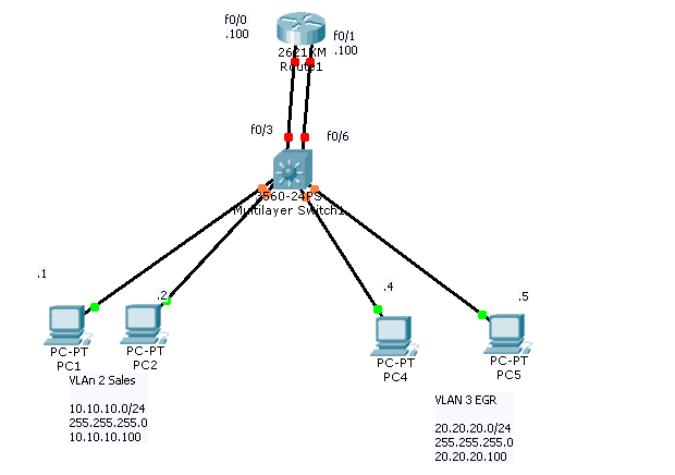
To see how router on a stick works, build the following topology:
First we need to change port fa0/24 to be a trunk port. We will be using 802.1q as the trunking encapsulation.
Switch#conf t
Enter configuration commands, one per line. End with CNTL/Z.
Switch(config)#int fa0/24
Switch(config-if)#sw trunk encapsulation dot1q
Switch(config-if)#sw mode trunk
Switch(config-if)#
let’s check the result on Switch
Switch#show int trunk
| Port |
Mode |
Encapsulation |
Status |
Native vlan |
| Fa0/24 |
on |
802.1q |
trunking |
1 |
Switch#
Now, on the router we need to create the sub-interfaces for the two VLANs. A sub-interface is created by referencing the interface name followed by a dot, followed by a unique number in this format interface fa0/0.X We can choose any number for X and it does not have to be sequential. However, normally we want to match the sub-interface number with the VLAN number (known as VLAN ID).
Don’t forget to bring the physical interface up.
Let’s take a look:
Router>
Router>en
Router#conf t
Enter configuration commands, one per line. End with CNTL/Z.
Router(config)#int fa0/0
Router(config-if)#no shutdown
Router(config-if)#
%LINK-5-CHANGED: Interface FastEthernet0/0, changed state to up
%LINEPROTO-5-UPDOWN: Line protocol on Interface FastEthernet0/0, changed state to up
Router(config-if)#exit
After we bring the interface up, we create the sub-interfaces and indicated to which VLAN they belong to. We assign the Default Gateway IP address of the relevant VLAN to the sub-interface.
Router(config)#interface fa0/0
Router(config)#interface fa0/0.?
<0-4294967295> FastEthernet interface number
Router(config)#int fa0/0.2
Router(config-subif)#
%LINK-5-CHANGED: Interface FastEthernet0/0.2, changed state to up
%LINEPROTO-5-UPDOWN: Line protocol on Interface FastEthernet0/0.2, changed state to up
Router(config-subif)#encapsulation dot
Router(config-subif)#encapsulation dot1Q 2
Router(config-subif)#ip address 10.10.10.100 255.255.255.0
Router(config-subif)#exit
The number coming after encapsulation dot1Q must match the VLAN number (VLAN ID). 802.1q will TAG the traffic coming from the VLAN with the VLAN ID. The router looks at the TAG to determine which sub-interface the traffic associated with.
Here is the configuration for VLAN 3:
Router(config)#interface fa0/0.3
Router(config-subif)#
%LINK-5-CHANGED: Interface FastEthernet0/0.3, changed state to up
%LINEPROTO-5-UPDOWN: Line protocol on Interface FastEthernet0/0.3, changed state to up
Router(config-subif)#encapsulation dot1Q 3
Router(config-subif)#ip add 20.20.20.100 255.255.255.0
Router(config-subif)#end
Router#
%SYS-5-CONFIG_I: Configured from console by console
==================Here is our show run ====================
interface FastEthernet0/0
no ip address
duplex auto
speed auto
!
interface FastEthernet0/0.2
description this will act as DG=10.10.10.100 for VLAN2
encapsulation dot1Q 2
ip address 10.10.10.100 255.255.255.0
!
interface FastEthernet0/0.3
description This Will act as DG=20.20.20.100 for VLAN 3
encapsulation dot1Q 3
ip address 20.20.20.100 255.255.255.0
!
hint : make sure do not give IP address to physical interface f0/0 but you always assign it to sub-interface
Check to see if we have the subnets in the routing table:
Router#sh ip route
Codes: C – connected, S – static, I – IGRP, R – RIP, M – mobile, B – BGP
D – EIGRP, EX – EIGRP external, O – OSPF, IA – OSPF inter area
N1 – OSPF NSSA external type 1, N2 – OSPF NSSA external type 2
E1 – OSPF external type 1, E2 – OSPF external type 2, E – EGP
i – IS-IS, L1 – IS-IS level-1, L2 – IS-IS level-2, ia – IS-IS inter area
* – candidate default, U – per-user static route, o – ODR
P – periodic downloaded static route
Gateway of last resort is not set
10.0.0.0/24 is subnetted, 1 subnets
C 10.10.10.0 is directly connected, FastEthernet0/0.2
20.0.0.0/24 is subnetted, 1 subnets
C 20.20.20.0 is directly connected, FastEthernet0/0.3
Router#
Note that the router connects the subnets to the virtual sub-interfaces. Now the router can “Route” the traffic between different broadcast domains, although the traffic is physically coming and going over the same interface.
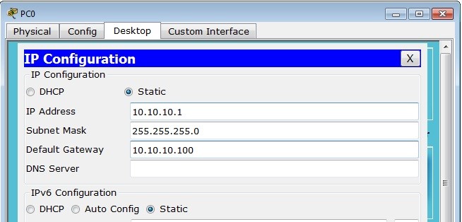
We must configure the PC’s with the correct IP address and Default Gateway values:
As before the switch is configured with the correct VLAN’s and interfaces have been assigned to them.
Switch#sh vlan br
| VLAN |
Name |
Status |
Ports |
| 1 |
default |
active |
Fa0/3, Fa0/6, Fa0/7, Fa0/8
Fa0/9, Fa0/10, Fa0/11, Fa0/12
Fa0/13, Fa0/14, Fa0/15, Fa0/16
Fa0/17, Fa0/18, Fa0/19, Fa0/20
Fa0/21, Fa0/22, Fa0/23, Gig0/1
Gig0/2 |
| 2 |
Sales |
active |
Fa0/1, Fa0/2 |
| 3 |
EGR |
active |
Fa0/4, Fa0/5 |
| 1002 |
fddi-default |
active |
|
| 1003 |
token-ring-default |
active |
|
| 1004 |
fddinet-default |
active |
|
| 1005 |
trnet-default Switch# |
active |
|
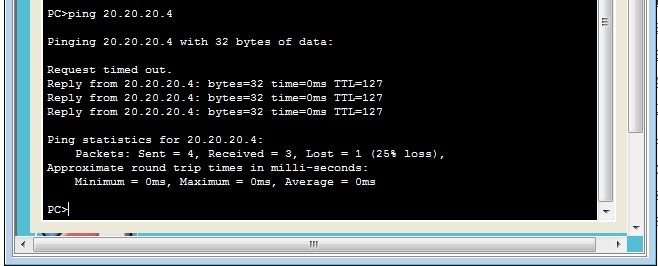
Ping test from the 10.10.10.0 subnet to the 20.20.20.0 subnet should succeed: