

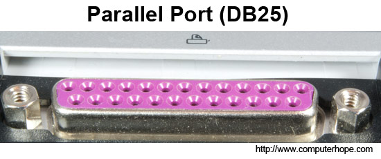
Less commonly referred to as the Centronics interface or Centronics connectorafter the company that originally designed it, the port was later developed by Epson. The parallel port is found on the back of IBM compatible computers and is a 25-pin (type DB-25) computer interface commonly used to connect printers to the computer. Below is an example of the DB25 interface found on the back of the computer.
Identifying
In the above graphic of a parallel port you can notice the DB25 parallel port connection is easy to identify and is often the biggest connection on the back of the computer. The connection is in the shape of the letter D, is a female connector, and has 25 holes.
Parallel port modes
The computer is capable of having the parallel port run at different modes depending on your needs and available resources. Some of these modes include: IEEE-1284 (Auto),Centronics mode, Nibble mode, Unidirectional (SPP), Bi-directional, EPP, and ECP.
Additional technical information
The DB25 connector has an 8-bit data bus, supported a maximum cable length of 15 feet; although there are 50 foot cables, it is not recommended that these cables be used as it can create poor connection and data signals. Below is additional information about each of the pins on this connector. Pin 1 through 25 identified in the image above.
| PIN | PURPOSE |
|---|---|
| Pin 1 | -Strobe |
| Pin 2 | +Data Bit 0 |
| Pin 3 | +Data Bit 1 |
| Pin 4 | +Data Bit 2 |
| Pin 5 | +Data Bit 3 |
| Pin 6 | +Data Bit 4 |
| Pin 7 | +Data Bit 5 |
| Pin 8 | +Data Bit 6 |
| Pin 9 | +Data Bit 7 |
| Pin 10 | -Acknowledge |
| Pin 11 | +Busy |
| Pin 12 | +Paper End |
| Pin 13 | +Select |
| Pin 14 | -Auto Feed |
| Pin 15 | -Error |
| Pin 16 | -Initialize Printer |
| Pin 17 | -Select Input |
| Pin 18 | -Data Bit 0 Return (GND) |
| Pin 19 | -Data Bit 1 Return (GND) |
| Pin 20 | -Data Bit 2 Return (GND) |
| Pin 21 | -Data Bit 3 Return (GND) |
| Pin 22 | -Data Bit 4 Return (GND) |
| Pin 23 | -Data Bit 5 Return (GND) |
| Pin 24 | -Data Bit 6 Return (GND) |
| Pin 25 | -Data Bit 7 Return (GND) |
Below is an explanation of each of the above purposes.
Pin1 – Data acknowledgement when the signal is low.
Pin 2 – 9 – Data transfer pins.
Pin 10 – Acknowledge that the data has finished processing and when the signal is high indicates ready for more.
Pin 11 – When the signal goes high indicate that the printer has accepted the data and is processing it. Once this signal goes low and Pin 10 goes high will accept additional data.
Pin 12 – Printer paper jam when signal is high or no signal if printer jam.
Pin 13 – When high signal printer is indicating that it is on-line and ready to print.
Pin 14 – When low signal PC has indicated that the printer inset a line feed after each line.
Pin 15 – Printer sends data to the computer telling it that an error has occurred.
Pin 16 – When low signal PC has requested that the printer initiate an internal reset.
Pin 17 – When low signal the PC has selected the printer and should in return prepare for data being sent.
Pin 18 – 25 – Ground.
What is the parallel port used for?
Today, the parallel port has widely been replaced by the USB port. However, below is a listing of various hardware components that can be purchased and used with the parallel port.
Printer – The most common use for the parallel port.
Scanner – Another commonly used parallel device is a parallel port scanner. Parallel port scanners are a popular alternative to SCSI scanners because of how easy they are to install.
External Drives – Another popular use of the parallel ports are external drives such as the Iomega Zip Drive, which can be removed from one computer and placed onto another.
Apple computers
The Apple Macintosh computers use SCSI as its interface, which is parallel, but a lot more flexible when compared to the parallel port used with IBM compatible computers. Apple computers have never used a parallel port.
Source By:<www.computerhope.com>
To Become Certified For CompTIA A+ Please Visit This Link ;
