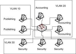
When you buy brand new switches all we need connect the PC to switch port and then PC can talk to each other ; but I can take a Switch like Cisco Switch and create a few VLAN ; such as
(Here is general Idea of VLAN)
VLAN 10 = Publishing
VLAN 20= Accounting
VLAN 30= security

| Vlan | Name | Status | Ports |
| 1 | Default | Active | Fa0/1, Fa0/2, Fa0/3, Fa0/4 Fa0/5, Fa0/6, Fa0/7, Fa0/8Fa0/9, Fa0/10, Fa0/11, Fa0/12
Fa0/13, Fa0/14, Fa0/15, Fa0/16 Fa0/17, Fa0/18, Fa0/19, Fa0/20 Fa0/21, Fa0/22, Fa0/23, Fa0/24 Gig0/1, Gig0/2 |
as we see all the ports are located in default VLAN one ; now I will create
two VLAN and assigned the port as follow
VLAN 2 EGR f0/1,f0/2
VLAN 3 Sales f0/4,F0/5
Here is the result after I have done above
Switch#show vlan brief
| Vlan | Name | Status | Ports |
| 1 | Default | Active | Fa0/3, Fa0/6, Fa0/7, Fa0/8Fa0/9, Fa0/10, Fa0/11, Fa0/12
Fa0/13, Fa0/14, Fa0/15, Fa0/16 Fa0/17, Fa0/18, Fa0/19, Fa0/20 Fa0/21, Fa0/22, Fa0/23, Fa0/24 |
| 2 | EGR | Active | Fa0/1, Fa0/2 |
| 3 | sales | Active | Fa0/4 Fa0/5, |
As we see now PC1 can talk to PC2 , and PC4 can talk to PC5 , but PC1 can not ping PC4 or PC5 since I need to have a router between them.
Here is the diagram after I put the router between them. Make sure give ip address of
10.10.10.100 to f0/0
20.20.20.100 to f0/1 and make sure turn on the port ; since by default all the ports are in shut down mode

Now lets look see if from PC1 can ping PC4.
As we see PC1 can not ping PC4 , so lets try to troubleshoot , go to PC1 and see if you can ping the
DG=10.10.10.100
PC>ipconfig
FastEthernet0 Connection:(default port)
Link-local IPv6 Address………: FE80::230:F2FF:FEA7:AB9D
IP Address………………….: 10.10.10.1
Subnet Mask…………………: 255.255.255.0
Default Gateway……………..: 10.10.10.100
PC>ping 10.10.10.100
Pinging 10.10.10.100 with 32 bytes of data:
Request timed out.
Request timed out.
Request timed out.
Request timed out.
Ping statistics for 10.10.10.100:
Packets: Sent = 4, Received = 0, Lost = 4 (100% loss),
As we see we cannot ping the DG
Why ?
Think of OSI Layer model .
Remember IP address is located on layer 3
- Physical Layer
- Data Link Layer ( look at your Switch)
- Network Layer
Now when I look at Switch and I type
Switch#show vlan brief
| Vlan | Name | Status | Ports |
| 1 | Default | Active | Fa0/7, Fa0/8Fa0/9, Fa0/10, Fa0/11, Fa0/12
Fa0/13, Fa0/14, Fa0/15, Fa0/16 Fa0/17, Fa0/18, Fa0/19, Fa0/20 Fa0/21, Fa0/22, Fa0/23, Fa0/24 |
| 2 | EGR | Active | Fa0/1, Fa0/2, Fa0/3, |
| 3 | sales | Active | Fa0/4, Fa0/5,Fa0/6, |
Now I should be able to ping from PC1 =10.10.10.1 to Pc4=20.20.20.4
PC>ping 20.20.20.4
Pinging 20.20.20.4 with 32 bytes of data:
Reply from 20.20.20.4: bytes=32 time=1ms TTL=127
Reply from 20.20.20.4: bytes=32 time=1ms TTL=127
Reply from 20.20.20.4: bytes=32 time=1ms TTL=127
Reply from 20.20.20.4: bytes=32 time=0ms TTL=127
Ping statistics for 20.20.20.4:
Packets: Sent = 4, Received = 4, Lost = 0 (0% loss),
Approximate round trip times in milli-seconds:
Minimum = 0ms, Maximum = 1ms, Average = 0ms
Now lets say instead of two VLAN , we have three or four VLAN ; in that case I can not out so many router between each VLAN , so cisco came with idea of Multi layer switch ( Cisco 3550, 3560 ,3575 and above) that allows you to be a layer 2 (switch) and layer 3 device (act as router) in that case we do not need a router ; which is but a Cisco 3550 and above then I can route packet from one vlan to another vlan. ( CCNA/CCNP concept)
Here how it looks like at Cisco Switch; when you buy brand new Switch (without configuration)
Want more information on how to become CompTIA Network+ Certified? Learn more!
Also published on Medium.


